Description
The engineering world frequently presents worm gearboxes and helical gear reducers as competing choices — but the helical-worm combination reducer challenges that framing entirely. The S Series takes the self-locking, right-angle, compact geometry of a worm gearbox and elevates its efficiency by 10–18 percentage points — not by abandoning the worm stage, but by adding a helical pre-stage that handles the high-speed input at rolling-contact efficiency before the worm stage handles the right-angle output at a lower, more favorable ratio. The result: a worm gear reducer that self-locks natively, outputs at 90°, achieves 100:1+ ratios in a compact envelope, and runs at 75–88% efficiency rather than the 60–75% of a single-stage worm at equivalent overall ratios. The S Series spans frame sizes S37 to S97, covering 200 to 4,200 Nm output torque and 13.65:1 to 197:1 ratios.

Key Specifications & Parameters of the S Series Helical-Worm Reducer
The S Series spans six frame sizes from S37 through S97, with a helical gear pre-stage (handling the high-speed input) and a worm gear final stage (handling the right-angle output at a lower ratio). All ratings per ISO 6336 (helical stage) and ISO 14521 (worm stage) at 1,450 rpm input.
| Frame | Output Torque | Ratio Range | Efficiency | Weight |
|---|---|---|---|---|
| S37 | 200 Nm | 13.65:1–197:1 | 78–88% | 8.5 kg |
| S47 | 360 Nm | 13.65:1–197:1 | 78–88% | 14 kg |
| S57 | 580 Nm | 13.65:1–197:1 | 77–87% | 22 kg |
| S67 | 980 Nm | 13.65:1–197:1 | 77–86% | 35 kg |
| S77 | 1,800 Nm | 13.65:1–197:1 | 76–86% | 58 kg |
| S97 | 4,200 Nm | 13.65:1–197:1 | 75–85% | 108 kg |
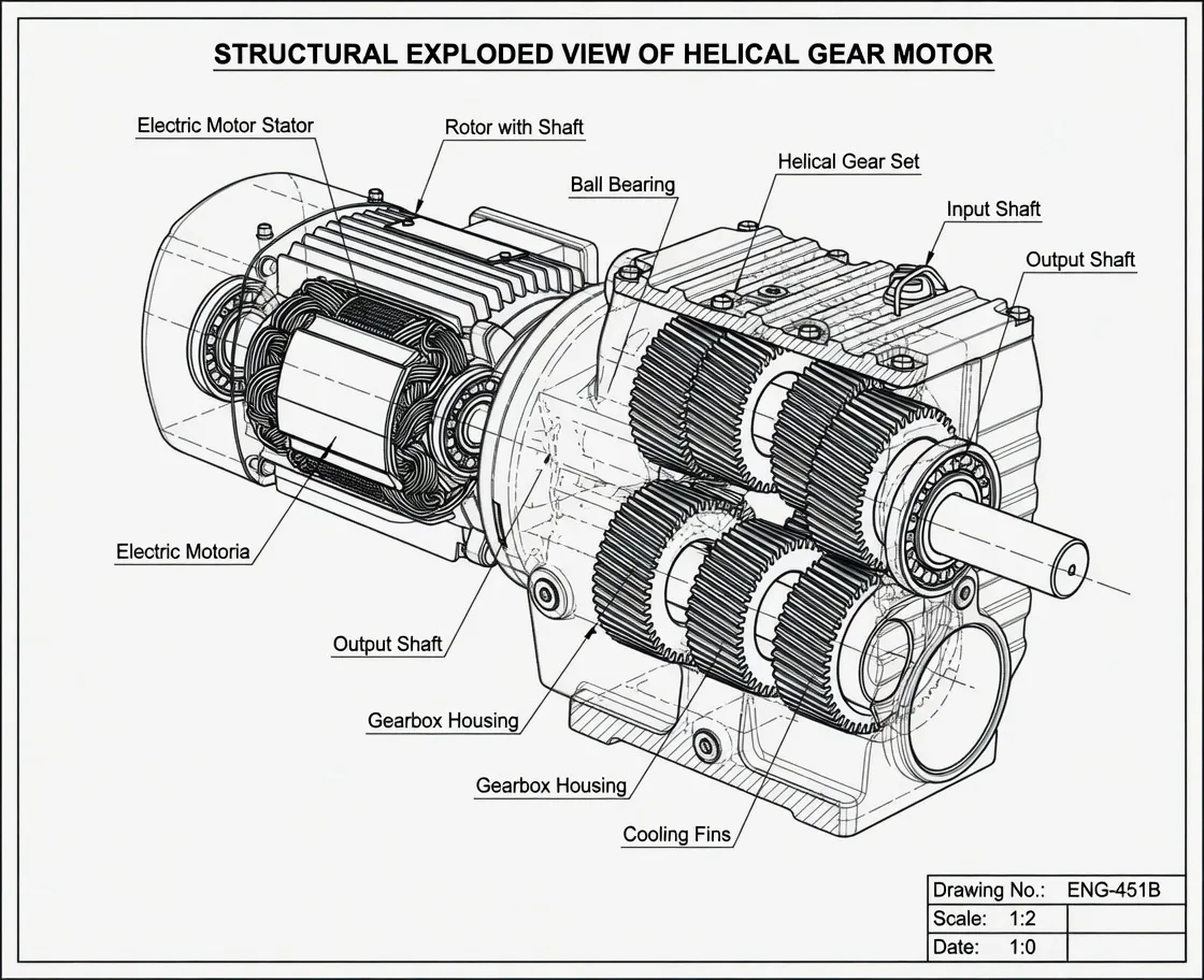
What Is a Helical-Worm Combination Reducer & How the Two-Stage Architecture Works
A helical-worm combination reducer splits the total reduction ratio across two gear stages with fundamentally different efficiency profiles — exploiting the strength of each architecture where it performs best:
- Helical pre-stage (input side): One or two stages of precision-ground helical gears handling the high-speed input (1,450 rpm from motor) at 95–97% per-stage efficiency via rolling contact. The helical stage reduces input speed to the range where the worm stage operates most efficiently (typically 200–500 rpm input to the worm).
- Worm final stage (output side): A single worm-and-wheel stage providing the 90° right-angle output. Because the worm stage now runs at a lower speed ratio (and therefore a larger lead angle) than it would if handling the full overall ratio alone, efficiency is significantly improved vs a single-stage worm at the same overall ratio.
The efficiency gain is quantifiable. For an overall 100:1 ratio:
- Single-stage worm at 100:1: Lead angle ~3°, efficiency 58–65%
- S Series helical-worm at 100:1 (helical 5:1 × worm 20:1): Worm stage at only 20:1 (lead angle ~11°, efficiency 76–82%) × helical 97% = combined 74–80% overall
The S Series also retains the two properties that make worm gearboxes irreplaceable in many applications:
- Native self-locking: The worm final stage self-locks at overall ratios ≥30:1 without any brake module — holding the output shaft position when the motor de-energizes.
- Right-angle 90° output: The worm final stage delivers the right-angle shaft offset inherent to worm-gear geometry.
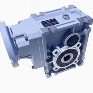
For engineers specifying right-angle drives where both self-locking and improved efficiency vs standard worm are required, the S Series is the natural upgrade path from the standard NMRV worm gearbox. For deeper technical background on helical-worm architecture selection and efficiency calculation methodology, see the helical-worm gearbox technical knowledge base.

Types of S Series Configurations
The S Series supports four standard configurations across all six frame sizes:
| Config. | Output | Mounting | Best Application |
|---|---|---|---|
| S – Solid shaft | Solid shaft | Foot + B5 | General right-angle drives |
| SH – Hollow shaft | Hollow shaft | Foot + B5 | Direct shaft mount |
| SA – Flange mount | Solid shaft | B5 flange only | Frame-integrated drives |
| SX – Gearmotor | Solid shaft | Pre-mated IE3 motor | Single-unit OEM supply |
The motor-integrated SX gearmotor is particularly popular for OEM equipment where the procurement and inventory simplification of one qualified assembly (motor + gearbox combined) outweighs the slight flexibility reduction vs separate sourcing. IE3 premium-efficiency motors are standard on SX units for EU Ecodesign Regulation (EU) 2019/1781 compliance.
S Series Production Process — Two-Stage Hybrid Manufacturing Flow
The S Series production flow combines the precision helical gear manufacturing sequence with the bronze-on-steel worm manufacturing process — two production streams that are integrated in the final assembly stage:
- Helical pre-stage gear manufacturing: 20CrMnTi forged-steel helical gear blanks, case-carburized to 0.8–1.2 mm case depth, quench-hardened to HRC 58–62, then CBN profile-ground to ISO 1328 Class 6 with Ra ≤0.4 µm. The helical pre-stage accounts for the majority of the efficiency improvement over single-stage worm — it must be manufactured to helical precision standards, not reduced-quality worm-line tolerances.
- Worm screw machining: 20CrMnTi steel case-hardened HRC 60–62 (case depth 0.7–1.0 mm), CBN profile-ground to ISO 1328 Class 7 with Ra ≤0.4 µm. The worm stage in an S Series runs at a lower ratio (and higher lead angle) than it would in an equivalent single-stage worm gearbox — reducing tooth-mesh contact force and extending worm-wheel service life.
- Bronze worm wheel casting: CuSn12Ni2 phosphor bronze centrifugally cast, HB 95–115. Because the S Series worm stage runs at a lower speed ratio than a single-stage worm at equivalent overall ratio, the sliding velocity is higher — requiring the full CuSn12Ni2 phosphor bronze specification rather than lower-grade bronze alloys.
- Aluminum housing die-casting: ADC12 aluminum die-cast housing dimensioned to accommodate the helical pre-stage behind the worm stage while maintaining a compact overall envelope compatible with standard IEC motor flange sizes.
- Integrated assembly: Helical pre-stage assembled first with precision-matched tapered roller bearings, FKM double-lip seals; worm stage assembled second in the right-angle output section. Sealed-for-life PAO synthetic lubricant fills both stages through a common reservoir.
- End-of-line testing: Each unit run-tested at rated load for 30 minutes. Temperature rise, backlash, sound level, and efficiency compared against acceptance limits. Sample-lot efficiency back-to-back test: minimum 75% at rated load at the relevant ratio.

How to Select the Right S Series Helical-Worm Reducer for Your Application
A seven-step selection procedure, with the architecture-choice comparison step placed first:
- Confirm S Series is the right architecture vs alternatives:
- Standard worm gearbox → upgrade to S Series when absorbed power above 2.2 kW at continuous duty above 4 h/day, and self-locking is still required
- S Series → upgrade to K Series bevel-helical when self-locking is NOT required and maximum efficiency priority
- S Series → ideal mid-tier between cost-optimized worm and premium bevel-helical
- Calculate continuous torque with service factor: Apply 1.5× for typical 8-hour OEM duty, 1.7× for 16-hour continuous, 2.0× for shock-loaded duty (conveyor jams, mixer viscosity peaks). Apply to the S Series output torque catalog rating.
- Determine output speed & ratio: S Series minimum ratio is 13.65:1 (higher than single-stage worm minimum 5:1). If ratio below 13:1 is needed, single-stage worm or inline helical is the correct specification. For ratios 14:1–197:1 with right-angle self-locking output, S Series is the primary candidate.
- Verify self-locking requirement: Self-locking in the S Series activates through the worm final stage at overall ratios ≥30:1. At ratios below 30:1 (the 13.65:1–25:1 range), the S Series is NOT self-locking. Verify that your required ratio gives the worm stage a high enough individual ratio to self-lock.
- Confirm thermal rating: Because the S Series generates less heat per unit of input power than a single-stage worm at equivalent overall ratio, the thermal constraint is less binding. However, for 24/7 continuous-duty at absorbed power above 5.5 kW, verify the S Series thermal rating — it is still lower than an equivalent bevel-helical K Series.
- Select configuration: Solid shaft (S/SA) for coupled drives; hollow shaft (SH) for direct shaft mount; SX gearmotor for single-unit OEM supply. Contact our helical-worm reducer engineering team with your torque, speed, and self-locking requirements for confirmation.
- Calculate TCO vs standard worm: At the application’s absorbed power and annual hours, calculate annual energy savings from the efficiency improvement (typically 10–18 percentage points). The S Series price premium over standard worm is typically recovered in 18–36 months for applications running more than 6 hours/day above 2.2 kW.
Compatible Components & Spare Parts We Stock
| Component | Specification | Use Case |
|---|---|---|
| Helical pre-stage gear set | 20CrMnTi, ISO 1328 Class 6 | Helical stage rebuild |
| Worm screw | 20CrMnTi, case-hardened, ground | Worm stage replacement |
| Bronze worm wheel | CuSn12Ni2, custom keyway | Most common service item |
| Matched worm and gear set | Lapped pair, per frame | Complete worm stage swap |
| FKM (Viton) seal kit | Double-lip, per frame size | Annual preventive replacement |
| PAO synthetic lubricant | ISO VG220, dual-stage rated | 8,000 hr change interval |
All S Series components are stocked as separate spares for OEM in-line replacement and field-service rebuild. The bronze worm wheel remains the first-to-wear component in the S Series, as in all worm-stage reducers. Because the S Series worm stage runs at a lower ratio (and therefore higher sliding velocity) than a single-stage worm at equivalent overall ratio, the worm wheel bronze grade must meet the full CuSn12Ni2 phosphor-bronze specification — standard or lower-grade bronze alloys accelerate wear at the elevated sliding velocities. For specifications on matched worm-and-gear pairs, industrial application case studies, and replacement sourcing guidance, see the industrial worm reducer specifications and case studies resource.
S Series Application Sectors — Where the Hybrid Architecture Wins
The S Series occupies a specific application niche — drives that need ALL of: right-angle 90° output, self-locking hold, and efficiency above 75%. The three requirements together define the S Series application space:
- Conveyors with inclined sections: Belt conveyors at slopes above 15° where a loaded belt must be held against back-slide during power-off or E-stop events. The S Series holds the belt natively; standard worm provides the same hold but at 10–18% higher energy cost in continuous running.
- Mixers & agitators in continuous-duty facilities: Chemical, food, and pharmaceutical agitators running more than 8 hours/day where self-locking prevents the agitator from slowly drifting backward when the motor is momentarily off between batches — and where efficiency-driven energy cost is tracked by plant energy management systems.
- Textile machinery drives: The S Series is a natural upgrade path from the single-stage worm gear reducer for textile machinery on applications where energy cost is relevant. Our worm gear reducer for textile machinery covers the single-stage textile-specific worm with lint-deflector seals; the S Series is the efficiency upgrade for high-duty-cycle textile production running more than 16 hours per day.
- Gate openers & access control (commercial / industrial duty): Commercial and industrial gate openers with 200+ cycles/day duty where the accumulated energy cost of continuous-duty operation becomes economically meaningful — and where self-locking remains a security-critical property.
- Food & packaging machinery lines: Continuous-running packaging line drives where right-angle layout matches the equipment geometry, self-locking ensures crisp stop behavior, and shift-length energy consumption is tracked in energy-management programs.
- Solar tracker drives (high-cycle): Commercial-scale solar tracker drives running near-continuous duty on sun-tracking algorithms where accumulated energy savings from improved efficiency compound across multi-MW installations.
- Ventilation & HVAC auxiliary drives: Damper actuators, fan-bypass valve drives, and cooling-tower auxiliary drives where right-angle layout and self-locking damper-position hold meet the HVAC system design requirements.
What Drive Engineers & OEM Equipment Teams Say About the S Series
“Upgraded 48 inclined conveyor drives from single-stage worm to S Series. Energy metering 12 months post-conversion: 14% electricity reduction on the drive circuit — within 1% of the efficiency-delta prediction. Self-locking still verified correct on all 48 positions at the 12-month check.”
— Roeland V., Energy Engineering Manager, Aggregates Processing, Netherlands
“Standardized S Series SX gearmotors on a new packaging line running 22 hours/day. The combination of improved efficiency over our previous worm gearbox fleet and self-locking that eliminates brake-module cost hit our TCO targets. Payback vs previous standard worm design: under 16 months.”
— Thomas P., Mechanical Engineering Lead, Packaging OEM, Belgium
“Specified S77 units on a chemical agitator fleet running 24/7 batch processing. The 15% efficiency improvement over the previous worm-gearbox spec translates to €28,000/year across the 28-agitator fleet. The S Series also runs noticeably cooler — lubricant change intervals are extended to 10,000 hours vs 6,000 hours for the previous worm design.”
— Marco F., Process Engineering Director, Specialty Chemicals, Italy
“Replaced SEW S-class worm-helical units on a gate automation system with 320 cycles/day duty. Drop-in compatibility on all positions. The self-locking security property passed the functional-safety review without supplementary brake module — same as the previous SEW units we were replacing.”
— Jan W., Systems Integration Engineer, Access Control OEM, Poland
Why Source the S Series Helical-Worm Reducer From Us
- Complete worm-and-helical architecture portfolio: The S Series sits in our complete right-angle reducer family alongside standard NMRV worm gearboxes, K Series bevel-helical, and F Series parallel-shaft reducers — each optimized for a different efficiency-cost-self-locking trade-off. A single source for every right-angle drive application reduces supply-chain complexity for OEMs and system integrators. Read more about our full gear reducer engineering range.
- SEW S-class dimensional interchangeability: The S Series follows the SEW-Eurodrive S-class dimensional convention for mounting hole pattern, shaft dimensions, and motor flange interface. For retrofit projects replacing failed SEW S37/S47/S57/S67/S77/S97 units, our S Series is direct mechanical drop-in for the majority of installations.
- OEM volume pricing for medium-scale programs: Annual contract pricing tiers at 50, 250, 1,000, and 5,000 unit volumes. OEM equipment programs at the 250+ unit tier receive dedicated production allocation and contract pricing that typically saves 28–35% vs single-unit pricing.
Frequently Asked Questions About the S Series Helical-Worm Reducer
1. What is the actual efficiency improvement vs a standard single-stage worm gearbox?
The improvement varies with overall ratio. At 50:1 overall: standard worm 68–74% vs S Series 80–86% — a 10–14 percentage point improvement. At 100:1 overall: standard worm 58–65% vs S Series 75–80% — a 13–18 percentage point improvement. The improvement is proportionally largest at high overall ratios, because the helical pre-stage allows the worm stage to run at a much more favorable (lower, higher-lead-angle) individual ratio. At low overall ratios (13:1–20:1), the single-stage worm already runs at a reasonably favorable lead angle and the S Series advantage narrows to 8–12 percentage points.
2. Does the S Series self-lock at all overall ratios?
No — self-locking requires the worm final stage to have a high enough individual ratio for its lead angle to fall below the friction-locking threshold. In an S Series at overall 14:1 (helical 2:1 × worm 7:1), the worm stage individual ratio of 7:1 has a lead angle above the self-locking threshold — NOT self-locking. At overall 60:1 (helical 3:1 × worm 20:1), the worm stage at 20:1 is firmly in the self-locking range. The general rule: overall ratio ≥30:1 in the S Series produces reliable self-locking. Contact our engineering team to confirm self-locking status for a specific S Series ratio selection.
3. Is the S Series mechanically interchangeable with SEW S-class worm-helical reducers?
Yes — our S Series follows the SEW S-class dimensional convention for mounting hole pattern, shaft dimensions, and motor flange. For retrofit installations replacing failed SEW S37/S47/S57/S67/S77/S97 units, the S Series is direct mechanical drop-in for the majority of positions. Confirm ratio and input rotation direction match before installation. For specific SEW model compatibility confirmation, contact our team with the SEW model number and ratio.
4. What service life can I expect from the S Series vs standard worm?
The S Series worm final stage actually runs at a higher sliding velocity than a single-stage worm at equivalent overall ratio — because the helical pre-stage has already reduced the speed, and the worm stage individual ratio is lower, producing a higher lead angle and higher sliding speed. This means the bronze worm wheel in the S Series wears slightly faster per hour of operation than in an equivalent single-stage worm. However, because the S Series runs cooler (generating less heat at equivalent absorbed power), lubricant degradation is slower and seal life is extended — so practical field service life is comparable: 20,000–30,000 hours for typical 8-hour single-shift applications.
5. When should I choose S Series over K Series bevel-helical?
Choose S Series when self-locking hold is required AND efficiency improvement over standard worm is valued. The K Series delivers higher efficiency (94–97% vs 75–88% for S Series) but cannot self-lock. If your application requires positional hold on motor de-energization (inclined conveyor, gate drive, vertical agitator hold between batches), S Series delivers both. If the application is purely horizontal continuous duty without hold requirement and maximum efficiency is the priority, K Series is the better specification.

Specifying a Helical-Worm Reducer for Your Right-Angle Self-Locking Application?
Send our drive specialists your duty cycle, absorbed power, ratio, self-locking requirement, and motor frame — we’ll return an S Series recommendation with TCO comparison vs standard worm, lead time, and volume pricing within one business day.