Description
A continuous-duty agitator consuming 11 kW and running 6,000 hours per year at a 30:1 right-angle output generates a stark efficiency choice: a bevel-helical right-angle gear reducer at 95% efficiency loses 0.55 kW as heat, costing approximately €396/year in wasted energy; an equivalent worm gearbox at 72% efficiency loses 3.08 kW, costing €2,218/year. Over an 8-year service life, that difference compounds to €14,576 per drive — enough to justify a bevel-helical gearbox’s price premium within the first 12–18 months of operation. The K Series bevel-helical right-angle gear reducer is engineered to capture this efficiency advantage across the full industrial right-angle drive market: frame sizes K37 to K187, output torque 400 to 62,000 Nm, ratios 5.36:1 to 197:1, at 94–97% efficiency throughout the range.

Key Specifications & Parameters of the K Series Bevel-Helical Reducer
The K Series spans eight frame sizes from K37 through K187, covering the torque range of most industrial right-angle continuous-duty drive applications. Carburized and ground helical pre-stages combined with a precision spiral-bevel final stage deliver right-angle output at helical-class efficiency. All ratings per ISO 6336 (helical gear load capacity) and ISO 10300 (bevel gear load capacity) at 1,450 rpm input.
| Frame | Output Torque | Ratio Range | Efficiency | Weight |
|---|---|---|---|---|
| K37 | 400 Nm | 5.36:1–197:1 | 95–97% | 16 kg |
| K47 | 700 Nm | 5.36:1–197:1 | 95–97% | 23 kg |
| K57 | 1,100 Nm | 5.36:1–197:1 | 95–96% | 38 kg |
| K67 | 1,900 Nm | 5.36:1–197:1 | 95–96% | 58 kg |
| K77 | 3,500 Nm | 5.36:1–197:1 | 94–96% | 96 kg |
| K87 | 6,500 Nm | 5.36:1–197:1 | 94–96% | 172 kg |
| K107 | 14,000 Nm | 5.36:1–197:1 | 94–95% | 340 kg |
| K187 | 62,000 Nm | 5.36:1–197:1 | 94–95% | 820 kg |
What Is a Bevel-Helical Gearbox & Why It Outperforms Worm at Continuous Duty
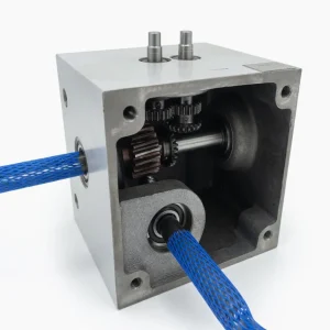
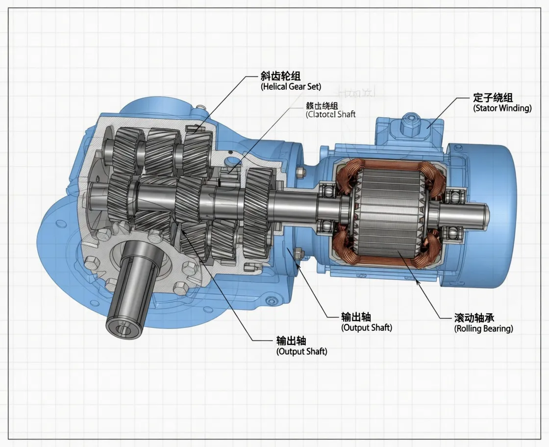
A bevel-helical right-angle gear reducer is a multi-stage reducer that combines carburized and ground helical gear pre-stages (for high-speed reduction with rolling contact and 96–98% per-stage efficiency) with a precision spiral-bevel final stage (for the 90° shaft offset with rolling-contact tooth engagement and 96–98% per-stage efficiency). The two architectures multiply: a three-stage K Series bevel-helical achieves 94–97% combined efficiency at 90° output — compared to 60–75% for an equivalent-ratio worm gearbox.
The critical distinction from a worm gearbox is the gear-mesh contact type. Bevel and helical gears engage through rolling contact — the tooth surfaces roll across each other with minimal sliding. Worm gears engage through sliding contact — the worm thread slides across the wheel face, generating heat and efficiency losses. Rolling contact means:
- Far lower heat generation at rated load — the K Series generates roughly 3–5% of input power as heat; an equivalent worm gearbox generates 25–40%.
- No thermal power-rating constraint — the K Series is mechanically-rated at all ratios; worm gearboxes at high ratios are frequently thermally-limited before the mechanical limit.
- No self-locking property — the K Series cannot back-drive hold without a brake module. For vertical-axis holds and gate drives, the worm gearbox remains the correct specification. For horizontal conveyors, fans, pumps, and mixers, self-locking is not required.
For a broader comparison of right-angle reducer architectures and selection methodology, the comprehensive right-angle gearbox selection guide covers the decision framework across worm, bevel-helical, and helical-worm configurations. For applications where self-locking or right-angle single-stage high-ratio is the primary requirement, our NMRV worm gearbox series remains the cost-optimal specification.

Types of K Series Configurations & Mounting Options
The K Series supports five standard configurations to match the full range of industrial right-angle drive geometries:
| Config. | Output | Mounting | Best Application |
|---|---|---|---|
| K – Solid shaft | Solid shaft | Foot + B5 | Agitators, screw conveyors, fans |
| KH – Hollow shaft | Hollow shaft + shrink-disc | Foot + B5 | Direct shaft mount, conveyors |
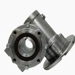
| KA – Flange mount | Solid shaft | B5 flange only | Frame-integrated drives |
| KHF – Hollow + torque arm | Hollow shaft | Hollow + torque arm | Belt conveyor head pulley |
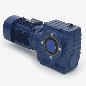
| KX – Gearmotor | Solid shaft | Pre-mated IE3 motor | Single-unit OEM supply |
K Series Production Process — Precision Bevel-Helical Manufacturing Flow
The K Series production flow extends the helical gear manufacturing sequence with the precision spiral-bevel stage — the most complex single element in the K Series, requiring dedicated bevel-gear generating machines:
- Helical gear blank forging & carburizing: 18CrNiMo7-6 forged-steel helical pre-stage gear blanks, carburized to case depth 0.8–1.4 mm, quench-hardened to HRC 60–62, then profile-ground to ISO 1328 Class 5 with Ra ≤0.6 µm.
- Spiral-bevel gear cutting: Gleason-generated spiral-bevel gears hobbed on dedicated bevel-gear cutting machines from 18CrNiMo7-6 forged blanks. Spiral angle 35° for optimal tooth overlap ratio and load-sharing. Each bevel pair matched and lapped together to achieve uniform tooth contact pattern.
- Spiral-bevel gear lapping & finishing: Each bevel pinion and wheel pair run together under graduated load in lapping compound. Final contact pattern checked against a Prussian-blue verification template; pairs failing the contact standard are rejected and re-cut.
- Cast-iron housing machining: EN-GJL-300 high-strength grey cast iron CNC-machined to H7 bearing-seat tolerances. The bevel-stage bearing seats require particularly tight coaxiality (0.008 mm runout) to maintain bevel-gear contact pattern under load.
- Assembly & lubrication: Tapered roller bearings on bevel-stage shafts (pre-loaded to manage bevel-gear thrust), angular contact bearings on helical input shaft. FKM (Viton) double-lip seals, ISO VG220 PAO synthetic lubricant fill.
- End-of-line testing: Each unit run-tested at 110% rated load for 20 minutes. Vibration spectrum (ISO 10816-3), temperature rise, and efficiency back-to-back test on sample lots (minimum 94% at rated load).

How to Select the Right K Series Bevel-Helical Reducer
A six-step procedure for K Series selection, with the architecture-decision step placed first:
- Confirm K Series is the right architecture: Specify K Series when — 90° right-angle output required, continuous duty above 4 hours/day at absorbed power above 2.2 kW, and self-locking hold is NOT required. If self-locking hold is required, specify worm gearbox or K Series + brake module. If inline layout is acceptable, R Series inline helical is more compact and lower cost.
- Calculate continuous & peak torque with service factor: Per AGMA 2001: uniform load 1.0–1.25, moderate shock 1.25–1.75, heavy shock 1.75–2.5. Apply service factor before comparing to catalog output torque rating.
- Determine output speed & ratio: Right-angle conveyor head drive: 30–100 rpm (ratio 15:1–48:1 from 1,450 rpm motor). Agitator vertical shaft: 60–180 rpm. Fan / pump direct coupling: 100–500 rpm. The K Series ratio range (5.36:1–197:1) covers all single-stage right-angle industrial drives.
- Select frame size: Match service-factor-adjusted torque to K Series catalog rating. The K Series is not thermally limited at any ratio (unlike worm gearboxes at high ratios) — frame sizing is governed purely by mechanical torque.
- Choose configuration: Solid shaft (K/KA) for coupling drives; hollow shaft with shrink-disc (KH) for direct shaft mount; torque-arm hollow (KHF) for belt conveyor head-pulley direct mount; KX gearmotor for single-unit supply chain.
- Verify IE3 compliance: For EU Ecodesign Regulation (EU) 2019/1781, confirm the KX gearmotor’s IE3 motor certification is documented. Contact our bevel-helical drive engineering team with motor frame, power, and EU compliance requirements.
Compatible Components & Spare Parts We Stock
| Component | Specification | Use Case |
|---|---|---|
| Spiral-bevel gear set (matched pair) | 18CrNiMo7-6, Gleason-generated, lapped | Major rebuild — bevel stage |
| Helical gear set (stage 1 & 2) | 18CrNiMo7-6, ISO 1328 Class 5 | Major rebuild — helical stages |
| Tapered roller bearings (bevel stage) | Pre-loaded pair, SKF/FAG | Service rebuild |
| FKM seal kit | Double-lip, per frame size | Annual preventive replacement |
| ISO VG220 PAO lubricant | High-load additive package | 8,000 hr change interval |
| Shrink disc assembly | Per KH/KHF frame size | Shaft mount replacement |
K Series vs Worm Gearbox — When Each Architecture Wins
The K Series and worm gearbox both deliver 90° right-angle output — but for fundamentally different reasons and in different application contexts. The decision framework:
| Criterion | K Series Bevel-Helical | Worm Gearbox (NMRV) |
|---|---|---|
| Efficiency (50:1) | 94–96% | 68–74% |
| Self-locking hold | No (needs brake) | Yes (≥30:1) |
| Single-stage 100:1 | Multi-stage needed | Yes, single stage |
| Unit cost | 2.5–3.5× worm | Lowest (baseline) |
| Continuous duty (>8h/day) TCO | Lower (energy savings) | Higher (energy cost) |
| Thermal power limit | Not applicable | Often binding at high ratio |
| Noise level | 64–72 dB | 55–62 dB (quieter) |
The practical outcome: specify K Series for continuous-duty right-angle drives above 2.2 kW absorbed power where efficiency TCO matters — conveyors, agitators, fans, pumps, roller-table drives. Specify worm gearbox for self-locking vertical holds, high single-stage ratios, quiet low-duty operation, or where unit cost is the primary driver. For detailed industrial application case studies comparing bevel-helical vs worm gearbox in conveyor and process-industry applications, see the industrial gear reducer application case studies.
K Series Application Sectors in Industrial Drives
- Continuous-duty right-angle conveyors: Head-pulley and tail drives on belt conveyors where motors are mounted perpendicular to the belt travel axis. KHF torque-arm hollow-shaft variant integrates directly onto the head-pulley shaft.
- Agitators & mixers: Vertical-shaft agitators in chemical, pharmaceutical, food, and water-treatment tanks where the right-angle output matches the vertical-shaft geometry and continuous duty makes efficiency economically significant.
- Industrial fans & blowers: Right-angle fan drives in HVAC, process ventilation, and combustion air systems. Low ratios (5:1–15:1) from K37–K57 cover most fan applications.
- Pump drives with 90° layout: Process pumps in petrochemical, water-treatment, and industrial cooling where right-angle motor layout suits the skid-mounting geometry.
- Screw conveyor right-angle drives: Horizontal screw conveyor drives where the motor must be mounted perpendicular to the screw shaft — common in grain handling, mineral processing, and cement.
- Cooling tower fan drives: Gearmotors for induced-draft cooling tower fans, where 24/7 continuous duty makes the K Series efficiency advantage particularly valuable.
- Rolling mill table drives: Roller-table drives in steel mill processing where the right-angle offset-shaft layout fits the roller-drive geometry.
What Drive Engineers & Plant Managers Say About the K Series
“Converted 36 right-angle conveyor drives from worm gearbox to K Series bevel-helical following an energy audit. Energy metering 18 months post-conversion shows 28% electricity reduction on the drive circuit — exactly in line with the efficiency delta the spec-sheet predicted.”
— Viktor H., Plant Energy Manager, Chemical Plant, Austria
“Specified K77 KH hollow-shaft units on a new agitator line running 20 hours/day. The payback analysis on the K Series premium vs worm gearbox was 11 months at our energy tariff. No thermal management issues across 14 months of continuous operation.”
— Claire M., Process Engineering Lead, Specialty Chemicals, Belgium
“Replaced SEW KA-series right-angle reducers on 24 cooling tower fans with K Series KA flange-mount. Direct dimensional drop-in on all 24 positions. Two seasons in continuous outdoor service, zero gearbox-related maintenance events — the SEW-compatible dimensional envelope is the deciding factor for retrofit projects.”
— Ahmed S., Facilities Engineering Manager, Petrochemical Plant, Qatar
“Built K57 KX gearmotors with IE3 motors into a new water-treatment screw-conveyor line. Single-unit procurement simplified the BOM — the IE3 efficiency certificates were ready immediately for our LEED documentation. 16 months in continuous operation, no unplanned downtime.”
— Jana K., Mechanical Engineer, Water Treatment OEM, Czech Republic
Energy Efficiency, EU Ecodesign Compliance & Sustainability
The K Series combined with IE3 premium-efficiency motors directly addresses the EU Ecodesign Regulation (EU) 2019/1781 and the broader industrial energy-reduction landscape:
- EU Ecodesign compliance: KX gearmotor units ship with IE3 premium-efficiency motor and EU Declaration of Conformity; IEC 60034-2-1 motor efficiency test report supplied with each unit.
- Energy-saving quantification: At K57 frame (1,100 Nm, typical agitator duty), 95% vs 70% worm at 11 kW absorbed: annual savings €1,430/drive at €0.12/kWh and 5,000 hours/year. Over 50 agitator drives: €71,500/year.
- Carbon footprint documentation: Product-level CO₂ intensity data available for scope 3 emissions reporting under GHG Protocol / CSRD requirements.
- ISO 14001:2015: Our manufacturing site operates under ISO 14001:2015 environmental management; 78% of cast iron sourced from recycled streams.
Why Source the K Series Bevel-Helical Reducer From Us
- Complete right-angle reducer portfolio under one supplier: We supply K Series bevel-helical (high-efficiency continuous duty), S Series helical-worm (hybrid efficiency + self-locking), and the full NMRV worm gearbox range — covering every right-angle drive requirement from a single source. Our planetary gearbox range extends coverage to high-precision servo applications. Read more about our full gear reducer engineering range.
- SEW K-series dimensional interchangeability: The K Series follows the SEW-Eurodrive K-series dimensional convention — the dominant installed base for bevel-helical reducers globally. Direct mechanical drop-in on the majority of retrofit projects.
- Volume pricing for fleet projects: Annual contract pricing tiers at 20, 100, 500, and 2,500 unit scope. Project-volume pricing typically saves 25–35% vs single-unit list pricing.
Frequently Asked Questions About the K Series Bevel-Helical Reducer
1. Can I add a brake to a K Series for self-locking on a vertical application?
Yes — a fail-safe spring-applied disc brake is available as an accessory module mounted between the motor and the K Series input shaft. For vertical hoists and lifts, a certified fail-safe brake is required regardless of gearbox type (even self-locking worm gearboxes require a supplementary brake in life-safety regulatory applications). Contact our team for the appropriate brake-module sizing for your application.
2. Is the K Series dimensionally interchangeable with SEW-Eurodrive K-series?
Yes — our K Series follows the SEW K-series dimensional convention for mounting hole pattern, output shaft dimensions, and motor flange interface. For retrofit projects replacing SEW K37/K47/K57/K67/K77/K87/K107/K187 units, our K Series is direct mechanical drop-in for the majority of installations. Confirm input rotation direction and ratio before installation; contact our team with the SEW model number for specific compatibility confirmation.
3. What is the payback period for upgrading from worm to K Series bevel-helical?
Payback depends on duty cycle and power. For 24/7 continuous-duty applications above 5.5 kW absorbed load at 50:1 ratio, typical payback is 8–14 months. For 16-hour two-shift applications above 3 kW, payback is 12–22 months. For intermittent-duty below 4 hours/day or below 2.2 kW absorbed, payback extends beyond 4 years — in these cases worm gearbox remains more cost-effective.
4. Does the K Series require more maintenance than a worm gearbox?
No — both require lubricant changes at similar intervals (8,000 hours) and annual seal inspection. The K Series has more components than a single-stage worm gearbox (multiple gear stages, more bearings) but generates far less heat per cycle, which is the primary driver of lubricant degradation. In practice, K Series lubricant condition is better preserved at equivalent service hours than worm gearbox lubricant at equivalent absorbed load and duty cycle.
5. What lead times apply for K Series standard vs custom configurations?
Standard K Series bare-shaft units (K, KA) in common ratios and smaller frame sizes (K37–K67) ship from semi-finished inventory within 2–3 weeks. Larger frames (K77, K87, K107, K187) align with 4–6 week production schedules. KHF torque-arm configurations add 1 week. KX gearmotor configurations add motor procurement time (2–3 weeks for IE3 standard motors). For project scope (20+ units), dedicated production allocation is available.

Specifying a High-Efficiency Right-Angle Reducer for Your Continuous-Duty Project?
Send our drive specialists your application duty cycle, absorbed power, output speed, and motor frame — we’ll return a K Series recommendation with payback analysis vs worm gearbox, lead time, and volume pricing within one business day.