
A modern utility-scale wind turbine at 4 MW nameplate rating sits 120 to 140 meters above ground level on a tower structure that must continuously yaw the nacelle into the prevailing wind direction to maintain rotor capture efficiency across constantly shifting wind conditions. Each turbine deploys 4 to 8 yaw drive units distributed around the yaw bearing periphery, working in coordinated synchronization to rotate the entire 350-tonne nacelle through 360° at controlled speeds of 0.5 to 1.5° per second. Across the 20-year project economic life that defines wind farm financial models, each yaw drive accumulates more than 5,000 cumulative direction-change cycles while subjected to peak shock loading events from wind gust transitions that produce 4 to 7× steady-state torque spikes during sudden wind direction shifts. Failure of any single yaw drive places the turbine into yaw-error fault condition that either stops the unit completely or restricts operation to reduced output, with each failure event typically removing the unit from production for 3-5 days while crane mobilization and replacement crew access protocols complete — translating to substantial energy yield loss across the 4 MW nameplate. Properly specified wind turbine yaw drive equipment — engineered around multi-stage planetary reduction with the torque density and shock-loading resilience that 20-year nacelle service demands — eliminates the recurring drive replacement cycle that the original generation of yaw drive specifications produced at year 7-9 service.
This guide covers the unique drive duty profile of utility-scale wind turbine yaw systems, addresses the wind shock loading and elevated nacelle service environment, walks through selection criteria balancing torque density with shock-loading resilience, and provides a maintenance roadmap suitable for the access constraints of nacelle-mounted equipment at hub heights above 100 meters. Audience: wind turbine OEM engineers, wind farm O&M specialists managing yaw drive replacement specifications, and procurement leads sourcing replacement drives for installed wind turbine fleets.
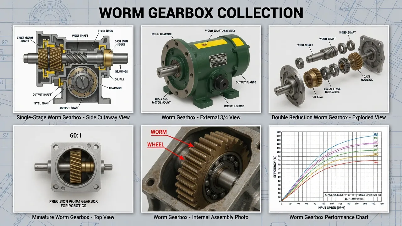
What Drive Demands Distinguish Wind Turbine Yaw from Industrial Service?
Wind turbine yaw drives combine four operational characteristics that no industrial application produces at the same intensity. The first is the torque density requirement: nacelle space constraints at hub heights above 100 meters limit the physical envelope available for each yaw drive to compact dimensions while the rotational torque required to yaw a 350-tonne nacelle through 360° reaches 35,000 to 65,000 Nm at the yaw bearing periphery. Distributing this peripheral torque across 4-8 yaw drive units means each drive must deliver 4,500 to 16,000 Nm output torque from a physical envelope smaller than what the same torque would require in any general-purpose industrial application. Multi-stage planetary reduction architecture delivers this torque density through compact concentric gear stages rather than the radial extension of worm gear architecture.
The second characteristic is the wind gust shock loading: sudden wind direction changes produce peak yaw torque events 4-7× steady-state during the 1-3 second transition window before yaw control logic responds, with the shock loading transmitted directly to the yaw drive train through the yaw bearing. The third characteristic is the access constraint at hub height — yaw drive replacement requires either crane mobilization to lift the entire nacelle to ground level (24-72 hour event) or specialized crew access protocols to perform in-nacelle drive replacement (4-6 day event) — both options expensive enough that wind farm operators specify drive equipment for the longest practical service life rather than minimum capital cost. The fourth is the temperature environment: nacelle interior temperatures range from -30°C in continental winter conditions through +55°C during summer operation when generator and gearbox heat plus solar gain on the dark nacelle exterior raise interior temperatures substantially above ambient. The right wind turbine yaw drive worm gearbox selection addresses torque density, shock loading capacity, multi-decade reliability, and wide temperature operation simultaneously per renewable energy drive technical references.
How Does Multi-Stage Planetary Architecture Address Wind Turbine Failure Modes?
Compact Torque Density for Hub-Height Installations
Multi-stage planetary reduction packs very high reduction ratios (typically 1:80 to 1:400) into compact concentric gear envelopes appropriate for the limited space available inside utility-scale wind turbine nacelles. The planetary architecture distributes loading across three or more planet gears at each reduction stage, sharing the total torque load across multiple meshing surfaces rather than concentrating loading at a single mesh point. This load sharing produces the torque density (Nm per kg of drive mass) required for hub-height installations where every kilogram of nacelle equipment translates to additional tower structural cost.
Hardened Steel Construction Resists Wind Gust Shock
Wind direction transitions produce peak shock loading events 4-7× steady-state torque during the 1-3 second response window before yaw control logic catches up. Multi-stage planetary architecture using case-hardened steel sun gears, planet gears, and ring gears (typical 20MnCr5 or 18CrNiMo7-6 case-hardened to HRC 58-62 surface hardness with HV 350-450 core hardness) handles peak shock loading without permanent deformation. The hardened steel construction sustains the cumulative cyclic peak loading across the 5,000+ direction-change events of the 20-year service life without fatigue failure.
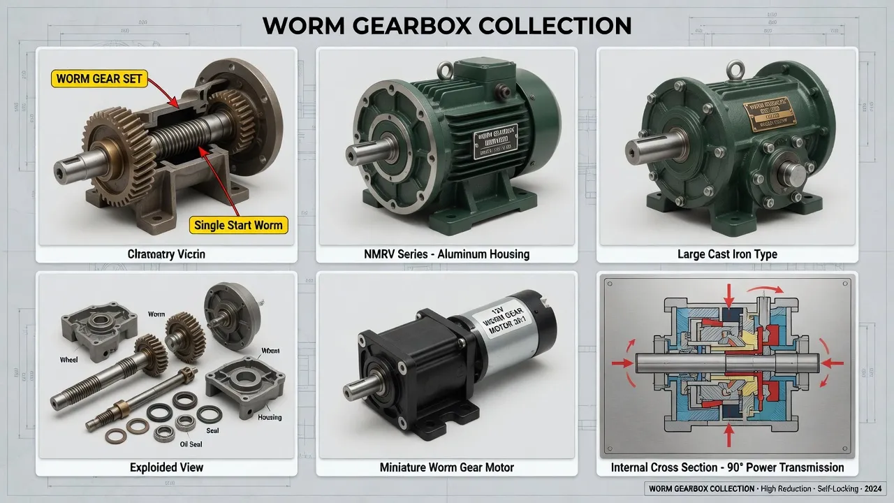
Technical Parameters: Wind Turbine Yaw Drive Specification Window
The table below summarizes specifications distinguishing wind turbine yaw drives from generic industrial planetary alternatives. Values reflect ISO 6336 gear rating combined with wind energy industry conventions for shock loading and 20-year nacelle service.
| Parameter | Yaw Drive Spec | Generic Planetary |
|---|---|---|
| Architecture | Multi-stage planetary, output pinion | Single or 2-stage planetary |
| Reduction ratio | 1:80 to 1:400 | 1:5 to 1:100 |
| Output torque (rated) | 4,500 – 16,000 Nm | 200 – 4,000 Nm |
| Peak shock capacity | 7× rated, no permanent damage | 2× rated typical |
| Operating temperature | -30 °C to +55 °C nacelle | -10 °C to +60 °C |
| Service factor | 2.5 minimum, 3.0 recommended | 1.0 – 1.25 typical |
| Lubricant | Synthetic PAO ISO VG 220 | Mineral oil typical |
| Design service life | 20 years (~5,000 cycles) | 10 – 15 years |
The single specification most often miscalculated on wind turbine yaw drive projects is the peak shock loading capacity. Generic planetary gearboxes catalog 2× rated output torque as peak shock capacity — completely inadequate for wind turbine yaw service where direction transitions produce 4-7× peak events. Yaw-grade planetary drives carry peak shock capacity ratings of 7× rated output without permanent damage, achieved through case-hardened gear surface treatment plus oversized bearing arrangements that distribute peak loading across multiple support points. Drives sized to general industrial peak shock capacity fail through cumulative cyclic fatigue within 6-9 years of wind service rather than reaching the 20-year project life target.
Application Matrix: Where Wind Turbine Yaw Drives Operate
Onshore Utility-Scale Yaw Drives (3-5 MW Class)
Onshore utility-scale wind turbines in the 3 MW to 5 MW nameplate range represent the dominant installed wind technology globally, with 4 to 6 yaw drive units per turbine handling the rotational torque distribution. Drive output torques range 4,500 to 9,500 Nm depending on turbine size, nacelle weight, and yaw control architecture. Onshore site conditions include continental temperature extremes, dust loading at agricultural sites, ice loading during winter conditions in northern markets, and varying lightning exposure that requires drive electrical isolation specifications matching turbine grounding architecture.
Offshore Wind Turbine Yaw Drives (8-15 MW Class)
Offshore wind turbines at 8 MW to 15 MW nameplate ratings represent the current frontier of wind technology deployment, with hub heights extending to 150-180 meters and rotor diameters above 200 meters. Yaw drive specifications scale upward with the turbine size, with output torques reaching 12,000 to 16,000 Nm per drive unit and 6 to 8 drives per turbine. Offshore installations add salt-fog corrosion exposure that requires upgraded sealing specifications and stainless steel mounting hardware. Maintenance access constraints multiply at offshore sites where every nacelle visit requires vessel mobilization, making 20-year service life targets particularly important for offshore yaw drive specifications.
Mid-Size Distributed Wind Turbines (500 kW to 2 MW)
Mid-size distributed wind turbines serve commercial and industrial customer applications including manufacturing facilities, agricultural operations, and remote power applications where utility-scale equipment exceeds the load profile. Drive specifications use scaled-down planetary architectures with output torques ranging 1,800 to 4,500 Nm. The drive duty profile parallels utility-scale equipment in cycle count and shock loading characteristics scaled to the smaller turbine size. Direct-drive permanent magnet generator architectures sometimes eliminate the main drive train but typically retain conventional yaw drive systems for nacelle rotation control.
Small Wind Turbines and Specialty Applications
Small wind turbines (under 100 kW) and specialty applications including testing platforms and instrumented research turbines use compact yaw drive systems matched to their smaller scale. Output torques typically run 600 to 1,800 Nm. The drive specifications scale the planetary architecture concepts of larger applications to smaller envelopes while maintaining the shock-loading resilience and 20-year service expectations that define wind sector drive equipment. Reference specialty wind energy drive guides for detailed application-specific sizing.
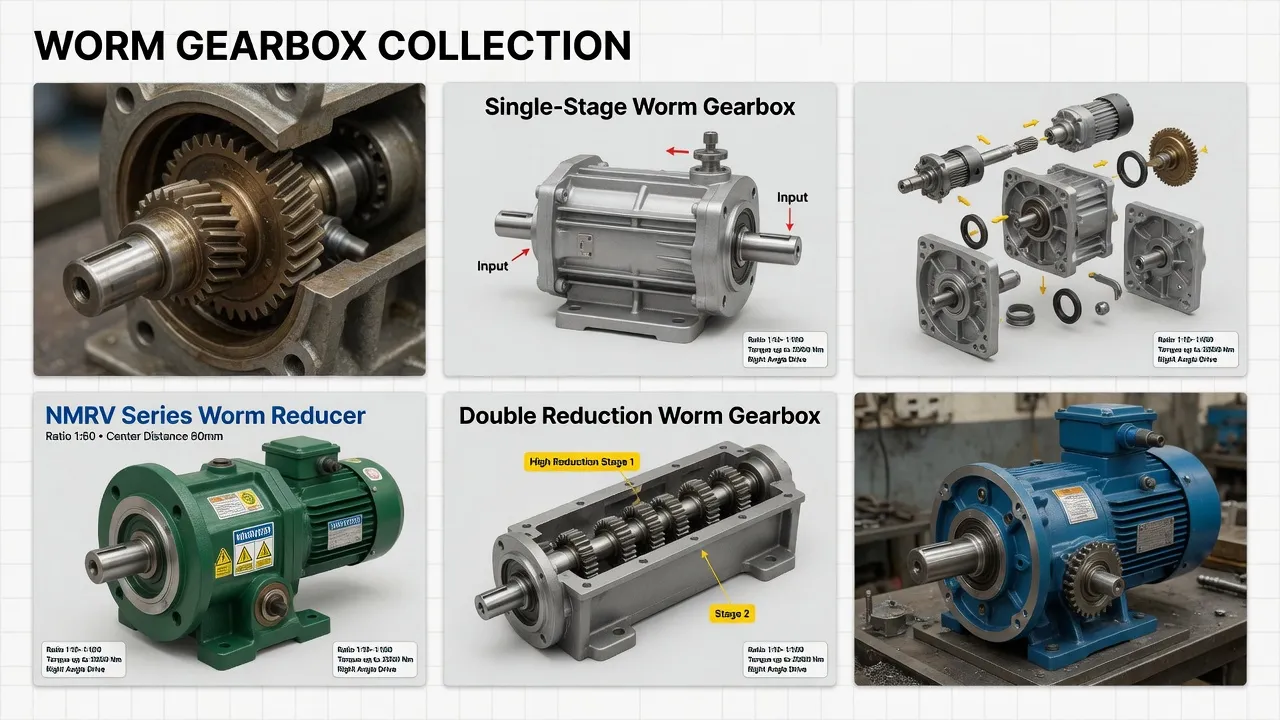
Selection Roadmap: Step-by-Step Workflow
The four-step procedure below covers wind turbine yaw drive selection from initial requirements documentation through commissioning verification.
Calculate Per-Drive Torque from Yaw System Architecture
Determine total yaw rotational torque required to overcome nacelle moment of inertia plus yaw bearing friction at maximum design wind speed. Distribute total torque across yaw drive count (typically 4-8 drives per turbine). Calculate per-drive output pinion torque accounting for yaw bearing gear ratio between pinion and bearing internal teeth. Document worst-case wind shock torque per drive — typically 4-7× steady-state during direction transitions in turbulent wind conditions.
Apply Service Factor 2.5 for Wind Shock Loading
Multiply calculated steady-state yaw torque by 2.5 for typical onshore utility-scale wind turbines, 3.0 for high-turbulence sites and class IA wind regions, and 3.5 for offshore installations. The resulting equivalent uniform-duty torque must fall within catalog rating with peak shock capacity of 7× rated output handling individual gust events. Service factor below 2.5 produces drives that fatigue within 6-9 years of wind service rather than reaching the 20-year project life target.
Specify Case-Hardened Steel and Synthetic Lubricant
Order case-hardened sun gears, planet gears, and ring gears (typical 20MnCr5 or 18CrNiMo7-6) hardened to HRC 58-62 surface with HV 350-450 core hardness. Specify synthetic polyalphaolefin (PAO) lubricant fill at ISO VG 220 with extreme-pressure additive package compatible with steel-on-steel meshing. Verify factory test reports include gear surface hardness verification per heat-treatment certification. The combined material specification plus EP synthetic lubricant delivers the 20-year fatigue life targets that wind sector drive economics require.
Verify Output Pinion Compatibility with Yaw Bearing
Confirm output pinion module, tooth count, profile, and quality grade match the yaw bearing internal gear teeth. Mismatched pinion-to-bearing engagement produces accelerated wear on both components within months of installation. Specify pinion case-hardened to HRC 58-62 with ground tooth profile per quality grade DIN 6 or better. Verify quench hardness depth meets fatigue life calculations under wind shock loading. Stainless steel mounting bolts (Grade 8.8 minimum) prevent galvanic seizure during the multi-decade nacelle service exposure.
Spare Parts Integration: Wind Farm Fleet Management
Wind farm O&M operations prioritize spare drive inventory matching the access economics of nacelle-mounted equipment — typically 2-4 percent of installed yaw drive count carried as forward-deployed spare stock at maintenance hubs serving each project area. The case-hardened steel sun gears, planet gears, and ring gears reach 25,000+ operating hours under proper synthetic lubrication — typically translating to 18-22 year service life before major rebuild becomes economically necessary, matching the 20-year project economic horizon assumed during financial close.
Premium-grade SKF or NSK tapered roller bearings throughout the planetary stages handle the combined radial and axial loads typical of yaw drive service with L10 fatigue life exceeding 25,000 hours under rated load. Output pinion shaft seal arrangements use double-lip Viton seals with stainless garter springs supporting nacelle service environments across the 20-year exposure. Gear oil sample analysis at 2-3 year intervals catches developing wear patterns 12-18 months before mechanical failure forces unscheduled outage, supporting the predictive maintenance approach that wind farm O&M operators favor over reactive replacement.
Spare parts kits combining complete planetary gear set, all bearing positions, output pinion shaft seals, gasket and o-ring kit, breather valve, and synthetic lubricant fill provide rebuild capability during scheduled major service events. Akgnx Co., Ltd ships kits packaged for wind farm O&M inventory practices with all gear components sourced from the same factory production runs to ensure dimensional consistency across rebuild cycles. Reference heavy-duty drive component specifications for detailed component-level technical data.
Cost & Sustainability: Total Ownership Across 20-Year Project Life
Wind farm developers and O&M operators evaluate yaw drive investments across the project economic life — typically 20 years matching standard PPA terms and turbine warranty periods. The table compares total cost of ownership for wind-grade planetary yaw drives against generic industrial alternatives across this horizon.
| Cost Component | Wind-Grade PGV | Generic Industrial |
|---|---|---|
| Initial unit price (FOB) | USD 3,800 – 14,500 | USD 1,800 – 6,200 |
| Service life in nacelle | 18 – 22 years | 6 – 9 years |
| Replacement frequency | 0.2× over 20 years | 2 – 3× over 20 years |
| Crane mobilization (per event) | Rare events | USD 80,000 – 250,000 |
| Lubricant interval | 3 years | Annual |
| 20-year cumulative TCO | ~ 1.2× installed cost | ~ 6.5× installed cost |
Sustainability and compliance documentation accompanies every wind-grade PGV planetary gearbox shipment. The housing carries CE marking per EU Machinery Directive 2006/42/EC and complies with RoHS Directive 2011/65/EU. Manufacturing follows ISO 9001:2015 quality management procedures with full material traceability from gear forging chemical composition through case-hardening heat-treatment records. Gear tooth geometry follows ISO 6336 quality grade with load capacity per ISO 6336 methodology adjusted for wind turbine cyclic shock loading. Optional IEC 61400-22 Type Certification supports projects requiring wind energy specific component qualification.
Synthetic polyalphaolefin (PAO) lubricant fills produce 70 to 80 percent less waste oil over the equipment service life compared to mineral oil alternatives requiring annual changes — biodegradable lubricant chemistry options meeting OECD 301 standards address environmental concerns particularly important at offshore installations subject to maritime environmental protection requirements. The 20-year drive service life eliminates the substantial lifecycle carbon footprint of multiple replacement cycles typical of generic industrial alternatives. Akgnx Co., Ltd manufactures wind-grade planetary yaw drives through a dedicated wind energy drive program serving wind turbine OEMs, EPC contractors, and wind farm O&M operators across major wind markets globally.
Customer Testimonials from Wind Energy Operations
“Our 320 MW onshore wind farm in continental Europe deploys 80 turbines at 4 MW nameplate, with 6 yaw drives per turbine for a total of 480 drive positions. We selected the PGV-based planetary yaw drives for our 2020 installation after experiencing accelerated failure rates on our prior wind farm using lower-grade specifications. Five years into operation, our yaw drive replacement rate is running 0.4 percent annually — substantially better than the 2-3 percent typical of the original specification.”
— O&M Director, European Wind Operator, Germany
“As a wind turbine OEM serving the 3-5 MW class onshore market, we evaluated multiple alternative yaw drive suppliers for our standard 4-drive nacelle architecture. Akgnx PGV-based drives passed our 8,000-cycle accelerated life test simulating 20-year wind direction-change duty plus class IA wind shock loading — measured backlash growth under 0.12° at test completion. Akgnx’s annual production schedule has held across two consecutive years for turbine shipments to our European and North American customer projects.”
— Director of Engineering, Wind Turbine OEM, Denmark
“We replaced original yaw drives across 36 turbines at our 2008-vintage onshore wind farm after the original supplier’s units showed accelerated failure beyond year 8. The Akgnx PGV-based replacement drives mounted to existing yaw bearing brackets without modification and supported our crew installation rate of 8 drives per crew-day during the swap-out program. The reduced subsequent failure rate has improved our project EBITDA by an estimated USD 380,000 annually across the remaining contract years.”
— Asset Manager, Wind Operations Portfolio, USA Texas
“Our 580 MW offshore wind farm faces salt-fog corrosion and limited maintenance access that retired our original drive supplier’s units within 8 years. The Akgnx upgraded specification with stainless mounting hardware, marine-grade sealing, and enhanced corrosion-resistant coating reached 11 years of installation service so far with zero corrosion-related yaw drive failures across the fleet. The improved drive availability translated to roughly 0.6 percent improvement in fleet capacity factor.”
— Operations Director, Offshore Wind IPP, United Kingdom
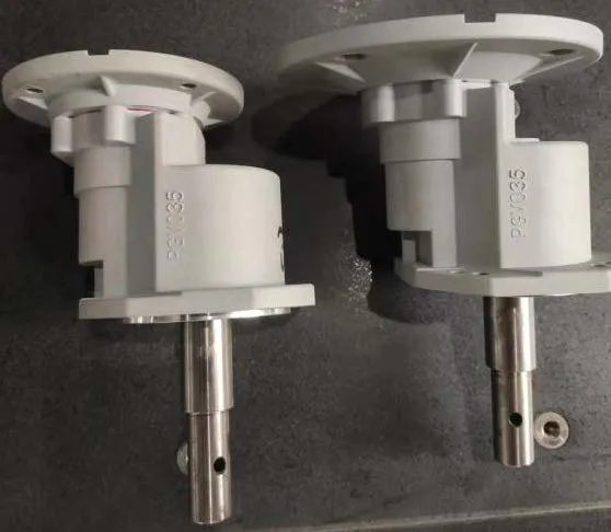
Recommended Drive: PGV Planetary for Wind Turbine Yaw Service
For wind turbine yaw drive applications across onshore utility-scale turbines, offshore installations, mid-size distributed wind, and specialty wind applications, the PGV Planetary Gearbox in wind energy specification targets the 20-year-service, shock-tolerant nacelle service class with engineering features specifically chosen to address the failure modes that retire generic industrial planetary alternatives within 6-9 years of wind turbine installation.
Specifications include cast iron housing with two-coat industrial epoxy paint plus salt-fog-resistant topcoat for offshore variant, multi-stage planetary gear architecture with case-hardened sun gears, planet gears, and ring gears (20MnCr5 or 18CrNiMo7-6 hardened to HRC 58-62 surface and HV 350-450 core), case-hardened output pinion ground to DIN 6 quality grade matching yaw bearing internal teeth, fluoroelastomer (Viton) double-lip output shaft seals with stainless garter springs, IP66 ingress protection for nacelle interior service, and synthetic polyalphaolefin (PAO) lubricant fill at ISO VG 220 with extreme-pressure additive package. Reduction ratios from 1:80 through 1:400 cover the full range of yaw drive duty across utility-scale and mid-size wind turbine applications. Output torque ratings reach 16,000 Nm continuous with peak shock capacity 7× rated output supporting wind direction transitions in turbulent conditions. CE marking, RoHS compliance, and ISO 9001:2015 quality system certification ship with every unit, with optional IEC 61400-22 Type Certification documentation available on EPC contractor request.
Beyond the PGV planetary frame, complete wind turbine yaw drive packages typically pair the gearbox with three-phase induction motors with electromagnetic brake assemblies, motor-mounted absolute encoders for yaw position feedback, weatherproof control connection junction box rated for nacelle service, and stainless steel A2 mounting hardware throughout. Akgnx Co., Ltd supplies matched drive packages for wind turbine OEMs and provides aftermarket replacement units for installed wind turbine fleets across major wind markets globally.
Specifying Yaw Drives for Wind Turbines?
Send turbine size, yaw architecture, design wind class, and per-drive torque target. We supply PGV-based planetary yaw drives engineered for 20-year onshore and offshore wind service with 7× peak shock capacity.
Frequently Asked Questions
© Akgnx Co., Ltd · About Us · Contact Us · [email protected]