
A 100 MW utility-scale solar installation deploying single-axis horizontal trackers across 250 hectares of mounting structure depends on roughly 350 to 500 individual slew drive units, each rotating its assigned tracker row through ±60° of azimuth tracking from sunrise to sunset every operating day. Across the project economic life — typically 25 to 30 years matching the financial models that justify utility-scale solar investment — each slew drive accumulates more than 9,000 cumulative tracking cycles while exposed to the full range of outdoor conditions including UV degradation, dust accumulation, thermal cycling from -20°C winter mornings to +65°C summer afternoons under direct solar load, hail impact events, and wind loading that produces peak structural torque events 3-5× the steady-state tracking requirement during gust events. The slew drive failure rate determines the project’s actual energy yield over its operating life — every drive failure removes one tracker row from optimal sun tracking until field maintenance can dispatch replacement, with each failure event typically costing 0.3-0.8 percent of that row’s annual energy production depending on outage duration and seasonal timing. Properly specified solar tracker slew drive equipment — engineered for the unique combination of continuous outdoor exposure, wind shock loading, and 25-year service expectations — protects the project yield economics that justify utility-scale solar deployment at financial close.
This guide covers the unique drive duty profile of utility-scale and commercial solar tracker installations, addresses the wind loading and outdoor exposure environment that defines tracker drive specifications, walks through selection criteria balancing torque capacity with multi-decade reliability, and provides a maintenance roadmap suitable for the limited service access of large-array solar installations. Audience: solar tracker OEM engineers, EPC project specifiers sourcing drive equipment for utility-scale projects, and O&M contractors managing replacement drive specifications for installed solar farm fleets.
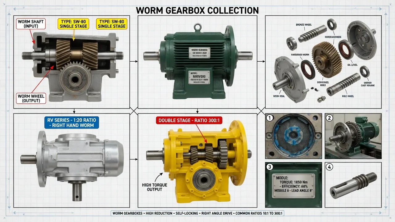
What Drive Demands Distinguish Solar Trackers from General Industrial Service?
Solar tracker slew drives combine four operational characteristics rare in any non-tracking application. The first is the 25-year service life expectation: solar PV project economics depend on tracker availability across the full equipment life that matches typical PPA terms, panel warranty periods, and project financing horizons. Drive failure rates that would be acceptable in 10-year industrial service translate to substantial yield loss when extrapolated to 25-year solar operation. The second characteristic is the wind loading shock profile: tracker structures act as effective sails during wind events, with peak torque transmitted to slew drives reaching 3-5× steady-state tracking torque during 100 km/h gust conditions. Drives sized for tracking torque alone fail through cyclic fatigue when subjected to repeated wind loading events across multi-decade exposure.
The third characteristic is the outdoor exposure environment that defines all utility-scale solar installations. Slew drives operate uncovered across the full range of project site conditions — ultraviolet exposure that degrades polymer seals and paint coatings, thermal cycling that produces fatigue stress at every dissimilar-material interface inside the drive, dust accumulation in arid sites that compromises sealing effectiveness, salt-fog exposure on coastal installations, and hail impact events that damage exposed components. The fourth is the maintenance access constraint: utility-scale solar installations span hundreds of hectares with thousands of tracker rows, making individual drive service prohibitively expensive relative to drive replacement cost. Drive specifications must support either complete drive-life service without intervention (the multi-decade target) or fast field replacement during scheduled service windows. The right solar tracker worm gearbox selection addresses 25-year reliability, wind loading capacity, and outdoor exposure simultaneously per renewable energy slew drive technical references.
How Do Worm Drives Address Solar Tracker Wind Loading Failures?
Self-Locking Holds Tracker Position During Wind Events
Solar trackers must maintain commanded position during wind events to protect both the tracker structure and the PV modules from wind-induced damage. Many tracker designs implement stow positions that minimize wind loading during severe weather, with drives required to hold the stow position absolutely against sustained wind torque until the storm passes. Self-locking worm gearboxes at reduction ratios above 50:1 hold the tracker position passively without external brake hardware, maintaining the stow position regardless of how long the storm event lasts. The static self-locking activates whenever the worm thread lead angle remains below the static friction angle of the meshing surfaces — a property of the gear geometry that does not depend on any active mechanism that could fail across the multi-decade service life.
Bronze Worm Wheel Absorbs Wind Shock Loading
Wind loading on tracker structures produces peak torque events that exceed steady-state tracking torque by factors of 3-5× during gust conditions. Bronze worm wheel construction (centrifugally cast tin bronze ZCuSn10P1 per ISO 1338) provides inherent shock absorption that protects both the slew drive internal components and the upstream electric motor from wind-induced damage. The bronze material yields slightly under extreme shock loading rather than fracturing, absorbing impact energy through localized plastic deformation that does not compromise gear meshing integrity across multi-decade service.
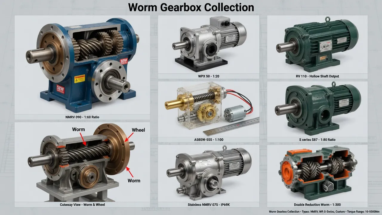
Technical Parameters: Solar Tracker Drive Specification Window
The table below summarizes specifications distinguishing utility-scale solar tracker drives from generic industrial alternatives. Values reflect AGMA 6034-B92 worm gear power rating combined with renewable energy industry conventions for wind loading and 25-year service expectations.
| Parameter | Solar Tracker Spec | Generic Industrial |
|---|---|---|
| Output configuration | Slew bearing or hollow shaft | 90° solid shaft typical |
| Reduction ratio | 50:1 to 100:1 self-locking | 5:1 to 100:1 |
| Output torque (rated) | 800 – 8,500 Nm | 200 – 2,000 Nm |
| Holding torque | 2 – 3× rated output | Self-locking only |
| Operating temperature | -30 °C to +75 °C | -10 °C to +60 °C |
| Sealing rating | IP66 plus UV-resistant | IP54 standard |
| Service factor (wind shock) | 3.0 minimum, 4.0 recommended | 1.0 – 1.25 typical |
| Design service life | 25 – 30 years (~9,000 cycles) | 10 – 15 years |
The single specification most often miscalculated on utility-scale solar projects is the service factor for wind shock loading. Catalog torque ratings assume uniform load conditions completely incompatible with outdoor tracker service where wind gusts produce peak torque events 3-5× steady-state during routine weather. Service factor 3.0 minimum covers typical solar tracker installations in moderate wind regions, with sites in high-wind regions (sustained design winds above 35 m/s per local building codes) justifying 4.0 service factor. Drives sized below 3.0 service factor fatigue within 8-12 years of solar service rather than reaching the 25-year project life target.
Application Matrix: Where Solar Tracker Drives Operate
Single-Axis Horizontal Trackers (HSAT)
Single-axis horizontal trackers represent the dominant utility-scale tracker architecture for current PV installations, rotating modules through ±60° of east-west tracking around a horizontal north-south axis. Each tracker row supports 60 to 120 PV modules (typical row lengths 60-120 meters) with the slew drive positioned at the center of the row distributing rotational torque to both wing sections. Drive output torques range 1,800 to 6,200 Nm depending on tracker row length, module count, and design wind region. The tracker geometry produces relatively predictable rotational torque profiles dominated by gravity component during morning and evening positions plus wind loading during all daylight conditions.
Dual-Axis Tracking Systems
Dual-axis trackers add elevation angle tracking to the azimuth tracking of single-axis systems, enabling the modules to track the sun’s full daily and seasonal path with precision targeting. The architecture deploys two independent slew drives per tracker — one azimuth (360° rotational) and one elevation (typically 0° to 70° tilt range) — both subjected to the same wind loading and outdoor exposure as single-axis equivalents. Output torques on dual-axis drives range 1,200 to 4,800 Nm depending on tracker size and module count. Dual-axis architecture sees deployment primarily in concentrating PV applications and in latitudes where the additional yield gain over single-axis tracking justifies the higher drive count and project cost.
Commercial Rooftop Tracking Systems
Commercial rooftop solar installations occasionally deploy compact tracking systems that extract 15-20% additional yield over fixed-tilt installations on suitable buildings. The drive specifications match utility-scale tracker requirements scaled to smaller individual array footprints, with output torques typically 600 to 2,400 Nm per drive. The rooftop application adds the constraint of acoustic noise compliance during early-morning and late-evening operation when surrounding buildings remain occupied — drive selection includes specific attention to quiet operation under low-speed tracking conditions.
Concentrating PV (CPV) and HCPV Trackers
High-concentration PV systems deploy precision dual-axis trackers with pointing accuracy requirements 0.1-0.3° to maintain optical alignment with concentrating reflectors and Fresnel lens assemblies. The drive precision requirement exceeds standard PV tracker specifications by an order of magnitude, with backlash limited below 0.05° and tracking smoothness requirements eliminating the cyclic torque variations acceptable in flat-plate PV installations. Output torques range 1,200 to 3,800 Nm with precision specifications dominating drive selection over absolute torque capacity. Reference precision drive component specifications for CPV-specific application sizing examples.
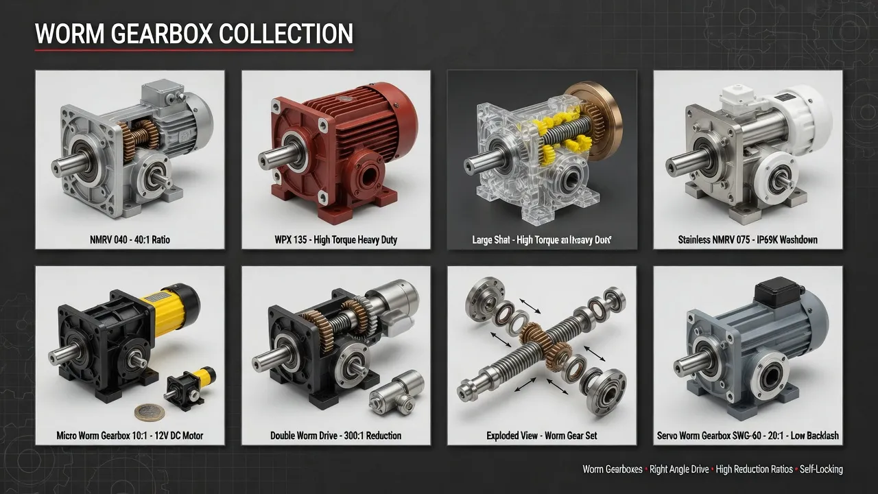
Selection Roadmap: Step-by-Step Workflow
The four-step procedure below covers solar tracker drive selection from initial requirements documentation through commissioning verification.
Calculate Tracker Wind Loading per Site Design Codes
Determine site design wind velocity per applicable building code (typical 30-40 m/s sustained for inland sites, up to 55 m/s coastal). Calculate peak rotational torque from wind force × tracker geometric centroid distance, accounting for tracker stow position effectiveness in reducing wind capture area. Document worst-case wind torque at operational tracking position (modules tilted at angle) plus stow position holding torque. Reference IEC 61400-style wind loading methodology adapted for tracker structures rather than wind turbine specifications.
Apply Service Factor 3.0 Minimum for 25-Year Service Life
Multiply calculated steady-state tracking torque by 3.0 service factor for typical solar tracker projects in moderate wind regions, 3.5 for arid high-temperature sites with sustained UV exposure stress, and 4.0 for high-wind sites and coastal installations with salt-fog exposure. The resulting equivalent uniform-duty torque must fall within catalog rating at chosen reduction ratio. Service factor below 3.0 produces drives that fatigue within 12-15 years rather than reaching the 25-year project economic horizon.
Specify UV-Resistant Materials and Wide-Range Synthetic Lubricant
Order UV-resistant paint topcoat plus EPDM or silicone seal materials rated for 25-year UV exposure. Synthetic polyalphaolefin (PAO) lubricant fill rated for -30 °C to +75 °C operating range covers desert site temperature extremes plus winter exposure in continental climates. Specify the lubricant requirement explicitly on procurement documentation rather than accepting default mineral oil fills that fail at temperature extremes typical of utility-scale solar installations.
Verify IP66 Sealing Plus Field Replacement Capability
Confirm the gearbox sealing package includes IP66 ingress protection plus UV-resistant breather configuration. Verify field replacement procedures support drive swap within scheduled service windows of 2-3 hours per drive position — the maintenance economics of utility-scale solar require fast individual drive replacement rather than extensive in-field component repair. Specify stainless steel mounting hardware throughout to prevent galvanic corrosion seizing during the multi-decade exposure period.
Spare Parts Integration: Utility-Scale Fleet Management
Solar farm O&M operations prioritize replacement stock matching the maintenance economics of utility-scale installations — typically dispatching field service crews to replace failed drives rather than repairing in-field. The worm shaft, machined from 20CrMnTi case-hardened steel with ground and polished thread surfaces hardened to HRC 58-62 per DIN 3974 quality grade Q8, reaches 30,000+ operating hours under proper synthetic lubrication and IP66 sealing protection — typically translating to 25-30 year solar service before major rebuild becomes economically necessary.
The worm wheel, centrifugally cast from premium tin bronze ZCuSn10P1 per ISO 1338 with ground tooth surfaces, reaches 25,000 to 30,000 operating hours under proper lubrication. Premium-grade SKF or NSK tapered roller bearings handle the combined radial and axial loads typical of slew drive service with L10 fatigue life exceeding 30,000 hours under rated load. UV-resistant fluoroelastomer (Viton) seal lips with stainless garter springs maintain ingress protection across the 25-year exposure period. Reference solar farm reducer specification guides for component-level technical details.
Spare drive inventory at utility-scale solar installations typically targets 1-2 percent of installed drive count as forward-deployed replacement stock at site, with the actual replacement rate during 25-year operation typically running 4-8 percent of installed quantity. Akgnx Co., Ltd ships drives packaged for solar farm spare parts inventory practices, with all units sourced from the same factory production runs to ensure dimensional consistency for interchangeable replacement across the project fleet.

Cost & Sustainability: Total Ownership Across 25-Year PPA
Utility-scale solar developers and EPC contractors evaluate tracker drive investments across the project economic life — typically 25 to 30 years matching the PPA term. The table compares total cost of ownership for solar-grade slew drives against generic industrial alternatives across this horizon.
| Cost Component | Solar-Grade Drive | Generic Industrial |
|---|---|---|
| Initial unit price (FOB) | USD 720 – 3,200 | USD 380 – 1,400 |
| Service life in solar field | 25 – 30 years | 8 – 12 years |
| Replacement frequency | 0.5× over 25 years | 2 – 3× over 25 years |
| Yield loss from outages | ~ 0.1% of project total | ~ 1.2% of project total |
| Field service labor cost | Minimal (rare events) | Substantial (frequent) |
| 25-year cumulative TCO | ~ 1.1× installed cost | ~ 4.8× installed cost |
Sustainability and compliance documentation accompanies every solar-grade drive shipment. The housing carries CE marking per EU Machinery Directive 2006/42/EC and complies with RoHS Directive 2011/65/EU. Manufacturing follows ISO 9001:2015 quality management procedures with full material traceability from bronze worm wheel chemical composition through case-hardened worm shaft heat-treatment records. Worm gear tooth geometry follows DIN 3974 quality grade Q8 with load capacity per AGMA 6034-B92 worm gear power rating methodology adjusted for solar tracker service factor.
Synthetic polyalphaolefin (PAO) lubricant fills produce 70 to 80 percent less waste oil over the 25-year equipment service life compared to mineral oil alternatives — a meaningful sustainability metric for utility-scale projects subject to lifecycle environmental assessment requirements during permitting and PPA finalization. The 25-year drive service life eliminates the lifecycle carbon footprint of multiple replacement cycles typical of generic industrial alternatives. Akgnx Co., Ltd manufactures solar-grade slew drives through a dedicated renewable energy drive program serving solar tracker OEMs, EPC contractors, and utility-scale solar O&M operators across major solar markets globally.
Customer Testimonials from Utility-Scale Solar Operations
“Our 240 MW utility-scale single-axis tracker installation deploys 720 slew drive units across 14 array blocks. We selected the KM-based slew drive package after evaluating four alternative suppliers across three test installations during 2021. Six years into operation, our drive failure rate is running 0.3 percent annually — within the project pro forma assumptions and substantially better than industry baseline data we used during financial modeling.”
— Asset Manager, Utility-Scale Solar Operator, Texas USA
“As a horizontal single-axis tracker OEM serving the utility-scale market, we evaluated multiple alternative slew drive suppliers for our standard tracker package. Akgnx KM-based drives passed our 30,000-cycle accelerated life test simulating 25-year tracking duty plus simulated wind shock loading — measured backlash growth under 0.08° at test completion. Our annual production schedule has held across three consecutive years for tracker shipments to North American and Australian utility-scale projects.”
— Director of Engineering, Solar Tracker OEM, Spain
“We retrofitted 1,840 tracker rows with replacement slew drives across our combined 380 MW solar portfolio after the original supplier’s units showed elevated failure rates 4-5 years into operation. The Akgnx KM-based replacement drives mounted to existing tracker brackets without modification and supported our O&M crew installation rate of 18 drive replacements per crew-day during the swap-out program. Documentation including AGMA calculation summary and 25-year accelerated life test data supported our financial review process.”
— O&M Director, Solar Operations Portfolio, Australia
“Our 60 MW commercial dual-axis tracking installation in a coastal site faces salt-fog exposure that retired our original drive supplier’s units within 6 years. The Akgnx upgraded specification with stainless mounting hardware and enhanced UV-resistant coating reached 9 years of installation service so far with zero corrosion-related failures. The reduced replacement frequency improved our project IRR by an estimated 40 basis points across the remaining contract life.”
— Managing Director, Independent Power Producer, Greece
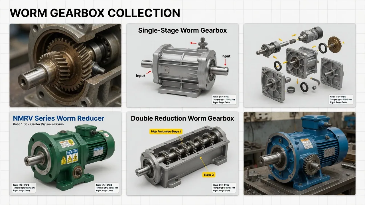
Recommended Drive: KM Helical Hypoid for Solar Tracker Slew Service
For utility-scale solar tracker applications across single-axis horizontal trackers, dual-axis tracking systems, commercial rooftop trackers, and concentrating PV installations, the KM Helical Hypoid Gearbox configured as a slew drive reduction stage targets the 25-year-service, wind-loaded outdoor service class with engineering features specifically chosen to address the failure modes that retire generic industrial alternatives within 8-12 years of solar field installation.
Specifications include cast iron housing with two-coat industrial epoxy paint plus UV-resistant topcoat rated for 25-year outdoor exposure, hardened steel hypoid gear set in the input reduction stage paired with worm-and-wheel self-locking output stage, fluoroelastomer (Viton) double-lip seals with stainless garter springs at all shaft penetrations, IP66 ingress protection plus UV-stabilized breather configuration, synthetic polyalphaolefin (PAO) lubricant fill rated for -30 °C to +75 °C operating temperature range, and stainless steel A2 mounting hardware throughout. Total reduction ratios from 1,500:1 through 5,400:1 deliver the slow rotational speeds typical of solar tracker tracking duty (±0.01 RPM at output during normal tracking) with self-locking holding capability across the full operational range. Output torque on combined hypoid-plus-worm slew drive packages reaches 8,500 Nm continuous with peak shock loading capacity 3-4× rated output. CE marking, RoHS compliance, and ISO 9001:2015 quality system certification ship with every unit.
Beyond the KM-based slew drive frame, complete solar tracker drive packages typically pair the gearbox with brushless DC or brushed DC motors for tracker control compatibility, weatherproof control connection box rated for 25-year outdoor exposure, and full stainless steel A2 mounting hardware throughout. Akgnx Co., Ltd supplies matched drive packages for solar tracker OEMs and provides aftermarket replacement units for installed utility-scale and commercial solar fleets across major solar markets globally.
Specifying Slew Drives for Solar Trackers?
Send tracker geometry, design wind region, project size, and required tracking torque. We supply KM-based slew drives engineered for 25-year utility-scale solar service with IP66 outdoor sealing and wind shock capacity.
Frequently Asked Questions
© Akgnx Co., Ltd · About Us · Contact Us · [email protected]