
A municipal wastewater treatment plant serving 250,000 residents processes 80,000 to 120,000 cubic meters of influent daily through primary and secondary clarifier basins where suspended solids settle out of the wastewater stream before discharge. Each clarifier deploys a center-driven rotating bridge mechanism that sweeps settled sludge toward the central collection sump while skimming floating scum from the surface — a continuous 24/7 rotation at 0.02 to 0.05 RPM that runs without interruption across the entire plant operating life. Drive failure on a clarifier means the entire basin becomes ineffective within 4-6 hours as solids accumulate without removal, eventually carrying through to subsequent treatment stages and risking discharge permit violations under EPA NPDES requirements or equivalent regional effluent standards. The drive operates submerged in the splash zone above sludge-laden water containing hydrogen sulfide, ammonia, and grit particles, with seal failure consequences ranging from contaminated lubricant within months to complete drive failure within weeks. Properly specified clarifier drive worm gearbox equipment — engineered for the unique combination of ultra-low-speed continuous duty, corrosive splash exposure, and 20+ year service life requirements — eliminates the unscheduled outage events that disrupt treatment plant compliance and operating cost projections.
This guide covers the unique drive duty profile of municipal and industrial wastewater clarifiers, addresses the corrosive splash environment and continuous-duty thermal management challenges, walks through selection criteria balancing torque capacity with extended service intervals, and provides a maintenance roadmap suitable for utility O&M staff managing limited overnight maintenance windows. Audience: water utility engineering managers, wastewater treatment plant operators, and consulting engineers specifying drive equipment for clarifier retrofit and new construction projects.
What Drive Demands Distinguish Clarifiers from General Industrial Service?
Clarifier drives combine four operational characteristics that distinguish them from any non-water-treatment application. The first is the ultra-low-speed continuous duty profile: clarifier rotation typically runs 0.02 to 0.05 RPM (one full rotation every 20 to 50 minutes) for 8,760 hours annually across 20+ year plant service lives. This combination of very low output speed and continuous duty produces unique thermal management challenges where the gearbox cannot rely on convective cooling from rotational airflow but must dissipate motor input heat plus internal friction losses through housing surface area alone. The second characteristic is the corrosive splash environment — clarifier drives mount on rotating bridge structures positioned directly above the wastewater surface, exposing the gearbox housing and shaft seals to splash containing hydrogen sulfide, ammonia, chlorides, and biological contaminants.
The third characteristic is the substantial torque overload protection requirement: clarifier mechanisms periodically encounter solids accumulation that produces torque spikes 3-5× steady-state operating torque. Drive specifications must include positive torque overload protection mechanisms — either mechanical shear devices or instrumented torque limiters — that protect the rotating bridge structure from drive train damage when accumulated solids resist the sweep mechanism. The fourth is the consequence of failure: clarifier outage of more than 4-6 hours cascades through the treatment plant to compromise effluent quality, with regulatory consequences ranging from operator notification requirements to permit violation penalties depending on duration and effluent impact. The right wastewater treatment worm gearbox selection addresses ultra-low-speed thermal management, corrosive splash protection, torque overload capacity, and 20-year continuous service simultaneously per water treatment drive technical references.
How Do Worm Drives Address Clarifier Failure Modes?
High Reduction Ratio Delivers Ultra-Low Output Speed
Clarifier rotation at 0.02 to 0.05 RPM requires very high total reduction ratios from typical electric motor input speeds (1,400 to 1,800 RPM) — total reduction values of 35,000:1 to 90,000:1 are typical. Multi-stage worm gearbox architectures pack these high reduction ratios into compact envelopes appropriate for clarifier center column installation while maintaining reasonable mechanical efficiency at each reduction stage. The triple-reduction worm architecture (three worm-and-wheel stages in series) delivers reduction ratios up to 90,000:1 from a single integrated drive package — eliminating the multi-component drive train complexity that single-stage alternatives would require.
Self-Locking Holds Position During Power Loss Events
Self-locking worm gearbox architecture at high reduction ratios maintains clarifier position absolutely during power outage events, preventing sludge sweep mechanism drift that could damage clarifier internal components. The static self-locking property of worm gear geometry holds position through the exact orientation occupied at power loss — important because clarifier sweep mechanisms include scum baffles and skimmer arms that must maintain specific angular relationships to avoid mechanical damage during restart sequences. Self-locking eliminates the need for active brake hardware that would add another failure mode in a continuous-duty drive application.

Technical Parameters: Clarifier Drive Specification Window
The table below summarizes specifications distinguishing clarifier drives from generic industrial worm gearbox alternatives. Values reflect AGMA 6034-B92 worm gear power rating combined with water treatment industry conventions for continuous service.
| Parameter | Clarifier Drive Spec | Generic Industrial |
|---|---|---|
| Output speed range | 0.02 – 0.05 RPM | 5 – 60 RPM typical |
| Total reduction ratio | 35,000:1 – 90,000:1 | 5:1 – 100:1 |
| Continuous output torque | 8,000 – 80,000 Nm | 200 – 4,000 Nm |
| Overload protection | Integrated torque limiter | External clutch typical |
| Service factor | 2.0 minimum continuous duty | 1.0 – 1.25 typical |
| Sealing rating | IP65 plus splash-resistant | IP54 standard |
| Annual operating hours | 8,760 hours (24/7) | 2,000 – 4,000 typical |
| Design service life | 20 – 25 years continuous | 10 – 15 years |
The single specification most often miscalculated on clarifier drive projects is the continuous duty service factor. Catalog torque ratings assume intermittent service patterns completely incompatible with 8,760 annual hours of clarifier operation. Service factor 2.0 minimum applied to steady-state operating torque covers typical municipal clarifier installations, with industrial wastewater applications carrying higher solids loading justifying 2.5 service factor. The continuous duty also requires synthetic lubricant fills with extended drain intervals — mineral oil alternatives requiring annual changes produce 8-12 lubricant change events across the project life that translate to substantial labor cost compared to synthetic fills with 5-year drain intervals.
Application Matrix: Where Clarifier Drives Operate
Primary Clarifier Center Column Drives
Primary clarifiers receive raw wastewater after preliminary screening and grit removal, settling out 30-50% of suspended solids before biological treatment. Center column drives mount on the clarifier center pier and rotate the entire scraper bridge through 360° at 0.02-0.04 RPM. Output torque requirements range 12,000 to 60,000 Nm depending on clarifier diameter (typical 20-50 meter diameter for municipal applications). The primary clarifier service environment includes higher organic loading and grit content than secondary clarifiers, with hydrogen sulfide concentrations reaching 25-40 ppm during summer operation. Drive specifications include enhanced corrosion protection and torque overload capacity to handle periodic grit accumulation events.
Secondary Clarifier Drives
Secondary clarifiers follow biological treatment processes (activated sludge or membrane bioreactor systems), settling biological flocs from treated wastewater before final disinfection. Center column drives operate at slightly higher rotational speeds than primary clarifiers (0.03-0.05 RPM) due to the lower density and easier settling characteristics of biological solids. Output torque requirements range 8,000 to 35,000 Nm depending on clarifier diameter. The biological floc nature of secondary clarifier solids produces lower mechanical loading than primary clarifier service but introduces specific concerns about sweep mechanism geometry that affect drive specifications and mounting arrangements.
Industrial Wastewater Clarifier Drives
Industrial wastewater treatment for petroleum refining, chemical manufacturing, pulp and paper, food processing, and metal finishing operations deploys clarifiers handling specific waste streams with chemical compositions distinct from municipal sewage. Drive specifications include compatibility with specific chemical exposure profiles — petroleum operations require oil-resistant seals, chemical manufacturing may require Hastelloy or stainless steel construction, pulp and paper handles fibrous suspended solids with potential for clogging events. Output torque requirements range 15,000 to 80,000 Nm depending on industrial process scale and waste stream characteristics.
Sludge Thickener Drives
Gravity sludge thickeners concentrate biological or chemical sludges from initial 0.5-1.0% solids concentration to 3-6% solids before subsequent processing. Drive specifications match clarifier service patterns at slightly lower rotational speeds (0.01-0.03 RPM) and higher torque requirements due to the denser sludge mat that develops in thickener service. Output torque requirements range 18,000 to 95,000 Nm. The continuous-duty nature plus extreme low-speed operation makes thickener drive specifications among the most demanding water treatment applications. Reference heavy-duty water treatment reducer specifications for thickener-specific application sizing.
Selection Roadmap: Step-by-Step Workflow
The four-step procedure below covers clarifier drive selection from initial requirements documentation through commissioning verification.
Calculate Sweep Torque from Clarifier Geometry and Sludge Loading
Determine sweep mechanism torque from clarifier diameter, scraper blade configuration, peripheral sweep velocity (target 1-3 m/min at clarifier rim), and design sludge density profile across the basin floor. Document worst-case torque events from grit accumulation, sweep restart after extended power outage, and seasonal solids loading variations. Industrial waste streams may require detailed CFD analysis for non-standard sludge characteristics.
Apply 24/7 Continuous Duty Service Factor
Multiply calculated steady-state sweep torque by 2.0 service factor for typical municipal clarifier installations, 2.5 for industrial wastewater with elevated solids loading, and 3.0 for sludge thickener service. The resulting equivalent uniform-duty torque must fall within catalog rating at chosen reduction ratio (35,000:1 to 90,000:1 typical). Service factor below 2.0 produces drives that fail through fatigue within 8-12 years rather than reaching the 20-year project life target.
Specify Integrated Torque Overload Protection
Order integrated mechanical torque limiter or instrumented torque transducer rated for protection at 2.5-3.0× nominal output torque. The torque limiter protects the clarifier rotating bridge structure from drive train damage during periodic grit or solids accumulation events that produce torque spikes beyond rated capacity. Verify the torque limiter setpoint matches the structural capacity of the clarifier bridge mechanism — the protection setpoint should activate before structural damage occurs.
Verify Synthetic Lubricant Fill and Splash-Resistant Sealing
Confirm synthetic polyalphaolefin (PAO) lubricant fill rated for 5-year drain intervals — mineral oil alternatives requiring annual changes produce substantial labor cost across 20-year service life. Verify IP65 ingress protection plus splash-resistant breather configuration that prevents wastewater aerosol contamination of the gearbox internal lubricant. Specify Viton fluoroelastomer seal materials rated for hydrogen sulfide and ammonia exposure typical of clarifier service environments.
Spare Parts Integration: Water Utility Asset Management
Water utility O&M operations prioritize spare drive inventory matching the consequences of clarifier outage — typically every utility carries one complete spare drive matched to each installed clarifier configuration, with spare wear components for the entire fleet. The case-hardened 20CrMnTi worm shafts in the multi-stage reduction architecture reach 35,000+ operating hours under proper synthetic lubrication and torque overload protection — typically translating to 22-25 year service life matching the typical wastewater treatment plant economic horizon assumed during capital investment planning.
The bronze worm wheels at each reduction stage, centrifugally cast from premium tin bronze ZCuSn10P1 per ISO 1338, reach 25,000-30,000 operating hours under proper lubrication. Premium-grade SKF or NSK tapered roller bearings throughout the multi-stage architecture handle the combined radial and axial loads typical of clarifier service with L10 fatigue life exceeding 30,000 hours under rated load. Viton fluoroelastomer seal lips with stainless garter springs maintain ingress protection across the wastewater splash environment exposure period. Reference heavy-duty drive component specifications for component-level technical details.
Spare parts kits combining all worm shafts, all worm wheels, complete bearing set, all shaft seals, gasket and o-ring kit, breather valve, torque limiter components, and synthetic lubricant fill provide complete rebuild capability during scheduled major service events. Akgnx Co., Ltd ships kits packaged for water utility inventory practices, with all wear components sourced from the same factory production runs to ensure dimensional consistency across rebuild cycles spanning multi-decade plant operating lives.

Cost & Sustainability: Total Ownership Across 25-Year Plant Life
Water utilities and consulting engineers evaluate clarifier drive investments across the plant economic life — typically 25 years matching depreciation schedules and capital investment planning horizons. The table compares total cost of ownership for clarifier-grade drives against generic industrial alternatives across this horizon.
| Cost Component | Clarifier-Grade MFV | Generic Industrial |
|---|---|---|
| Initial unit price (FOB) | USD 4,800 – 22,000 | USD 1,800 – 8,500 |
| Service life continuous duty | 22 – 25 years | 8 – 12 years |
| Lubricant change interval | 5 years synthetic | Annual mineral oil |
| Replacement frequency | 1× over 25 years | 2 – 3× over 25 years |
| Compliance event risk | Negligible | USD 5,000 – 50,000 per event |
| 25-year cumulative TCO | ~ 1.4× installed cost | ~ 6.8× installed cost |
Sustainability and compliance documentation accompanies every clarifier-grade drive shipment. The housing carries CE marking per EU Machinery Directive 2006/42/EC and complies with RoHS Directive 2011/65/EU. Manufacturing follows ISO 9001:2015 quality management procedures with full material traceability from bronze worm wheel chemical composition through case-hardened worm shaft heat-treatment records. Worm gear tooth geometry follows DIN 3974 quality grade Q8 with load capacity per AGMA 6034-B92 worm gear power rating methodology adjusted for clarifier continuous duty service factor.
Synthetic polyalphaolefin (PAO) lubricant fills support 5-year drain intervals producing approximately 80 percent less waste oil compared to mineral oil alternatives requiring annual changes — a meaningful sustainability metric for water utilities subject to environmental compliance reporting. The continuous-duty 25-year service life eliminates the lifecycle carbon footprint of multiple replacement cycles typical of generic industrial alternatives. Akgnx Co., Ltd manufactures clarifier-grade drives through a dedicated water treatment drive program serving municipal water utilities, industrial wastewater treatment operators, and consulting engineering firms specifying water treatment equipment.
Customer Testimonials from Water Treatment Operations
“Our regional wastewater treatment plant serves 280,000 residents through 6 primary clarifiers and 8 secondary clarifiers operating 24/7. We standardized on MFV-based clarifier drives in 2017 after experiencing reliability issues with the original generic-spec drives that came with the plant construction package. Eight years into operation, we’ve had zero unscheduled drive failures across the 14 installed positions. The synthetic lubricant 5-year drain interval also reduced our annual O&M labor by approximately 80 hours.”
— Operations Manager, Municipal Water Utility, USA Pacific Northwest
“As a water treatment equipment OEM serving industrial wastewater applications, we evaluated multiple alternative drive suppliers for our standard clarifier package. Akgnx MFV-based drives passed our pulp and paper industry qualification including 35,000-hour accelerated life test plus salt-fog corrosion exposure. We’ve shipped over 240 clarifier drive packages to pulp and paper, petroleum refining, and food processing customers across three years with zero warranty claims related to drive performance.”
— Director of Engineering, Industrial Water Treatment OEM, Canada
“We retrofitted clarifier drives across 4 wastewater treatment plants in our utility district after experiencing escalating maintenance costs on the original 1990s-vintage drives. The MFV replacement drives mounted to existing clarifier center column foundations without modification. Three years into the retrofit program, we’ve reduced clarifier-related unscheduled outages from approximately 6 events annually to zero, supporting our utility’s regulatory compliance metrics with state environmental authorities.”
— Asset Manager, Regional Water District, Texas USA
“Our refinery wastewater treatment system handles approximately 6,000 m³/day with elevated chloride and hydrogen sulfide exposure that retired our original drive supplier’s units within 6 years. The Akgnx upgraded specification with Viton seals and corrosion-resistant coating reached 11 years of installation service so far with zero seal failures. The reduced maintenance frequency improved our refinery wastewater system availability from 96% to over 99% across the operating period.”
— Wastewater Operations Lead, Petroleum Refinery, Saudi Arabia
Recommended Drive: MFV Flange Output for Clarifier Service
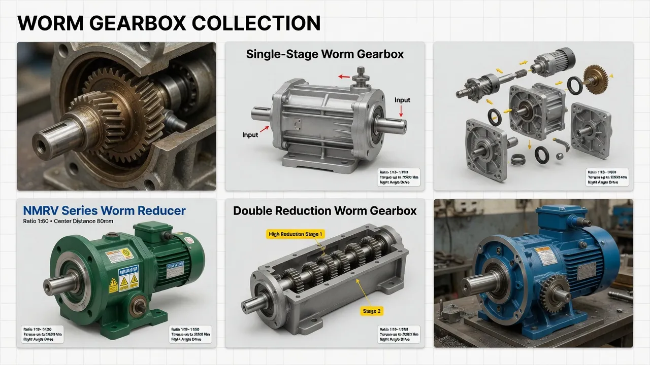
For municipal and industrial wastewater clarifier applications, sludge thickener installations, and dissolved air flotation (DAF) drives, the MFV Flange Output Worm Gearbox in clarifier service configuration targets the 24/7 continuous-duty, splash-protected, 25-year-service class with engineering features specifically chosen to address the failure modes that retire generic worm gearbox alternatives within 8-12 years of clarifier installation.
Specifications include cast iron housing with two-coat industrial epoxy paint plus chemical-resistant topcoat rated for hydrogen sulfide and ammonia exposure typical of wastewater service environments, multi-stage worm-and-wheel reduction architecture (typically triple-reduction for clarifier ratios) with centrifugally cast tin bronze ZCuSn10P1 worm wheels at each stage meshing with case-hardened 20CrMnTi steel worm shafts, integrated mechanical torque limiter or instrumented torque transducer rated for 2.5-3.0× nominal output torque protection setpoint, fluoroelastomer (Viton) double-lip seals with stainless garter springs at all shaft penetrations, IP65 ingress protection plus splash-resistant breather configuration, synthetic polyalphaolefin (PAO) lubricant fill rated for 5-year drain intervals, and stainless steel A2 mounting hardware throughout. Total reduction ratios from 35,000:1 through 90,000:1 deliver clarifier rotation across the full 0.02-0.05 RPM service range. Output torque ratings reach 80,000 Nm continuous with torque overload protection at 240,000 Nm peak. CE marking, RoHS compliance, and ISO 9001:2015 quality system certification ship with every unit.
Beyond the MFV-based gearbox, complete clarifier drive packages typically pair the gearbox with three-phase induction motors, weatherproof control connection junction box rated for splash service, position indication encoder for SCADA system integration, and full stainless steel A2 mounting hardware throughout. Akgnx Co., Ltd supplies matched drive packages for water treatment equipment OEMs and provides aftermarket replacement units for installed municipal and industrial wastewater treatment plant fleets across major water markets globally.
Specifying Drives for Wastewater Clarifiers?
Send clarifier diameter, design flow rate, sludge characteristics, and target output speed. We supply MFV-based clarifier drives engineered for 24/7 service across 25-year wastewater plant operations with integrated torque overload protection.
Frequently Asked Questions
© Akgnx Co., Ltd · About Us · Contact Us · [email protected]