
A radiology department operating across 4 CT scanners and 3 MRI systems performs approximately 120 imaging procedures per workday, with each procedure requiring patient table positioning accuracy below 0.1 mm to align anatomical regions of interest with the imaging gantry. The patient table drives must move 80-180 kg patient loads through translational strokes of 1,800-2,200 mm at controlled speeds 30-150 mm/s, then hold position absolutely during image acquisition windows of 8-45 seconds without measurable drift. Across an 8-hour shift, the table accumulates 200-400 positioning cycles per scanner, with cumulative cycle counts reaching 600,000-1,200,000 events across the 10-12 year scanner economic life. Drive failure during a scanning procedure forces patient repositioning and procedure restart — disrupting clinical workflow that already runs on tight scheduling, with each disruption affecting downstream patient appointments and diagnostic timeliness. Properly specified medical imaging table worm gearbox equipment — engineered for sub-millimeter precision, MRI magnetic field compatibility (where applicable), high-cycle quiet operation, and infection control compliance — eliminates the unscheduled outage events that disrupt clinical imaging schedules and diagnostic productivity.
This guide covers the unique drive duty profile of CT and MRI patient tables in clinical imaging departments, addresses the precision positioning requirements and clinical environment constraints, walks through selection criteria balancing positioning accuracy with quiet operation, and provides a maintenance roadmap suitable for hospital biomedical engineering departments managing imaging equipment fleets. Audience: medical imaging equipment OEMs, hospital biomedical engineers, clinical imaging system integrators, and consulting engineers specifying drive equipment for diagnostic imaging suite installations.
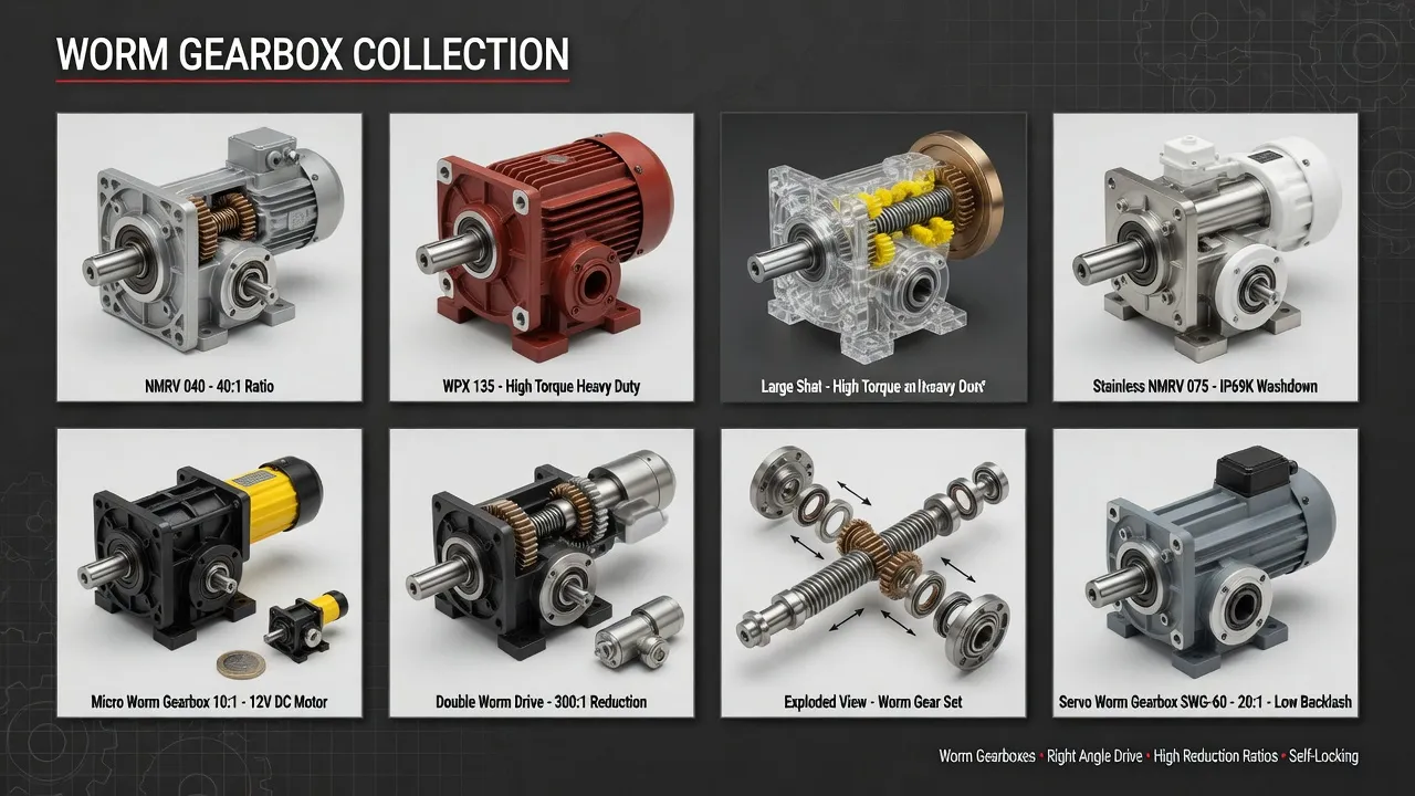
What Drive Demands Distinguish Medical Imaging Tables from General Service?
Medical imaging table drives combine four operational characteristics that distinguish them from any non-medical application. The first is the sub-millimeter positioning accuracy: CT and MRI imaging requires patient table position accuracy below 0.1 mm to maintain anatomical region alignment with the imaging gantry. Translation accuracy budget allocates this 0.1 mm total across servo loop accuracy, encoder resolution, drive backlash, and mechanical tolerance stack-up. Drive backlash specifications below 30 arcseconds form the foundation of the positioning accuracy budget at typical drive-to-screw mechanical advantages used in medical imaging table designs. The second characteristic is the absolute position holding requirement during image acquisition: during each CT or MRI image acquisition window (8-45 seconds), the table must hold position absolutely without drift exceeding 0.05 mm to prevent motion artifacts that compromise diagnostic image quality. Self-locking worm gear architecture provides this holding capability passively without continuous servo loop power application.
The third characteristic is the quiet operation requirement in clinical environments: imaging procedures occur in patient-occupied rooms where ambient sound levels above 50 dBA disturb patients and may compromise the relaxed state needed for quality imaging. Drive sound emission specifications typically require sub-50 dBA at 1 meter distance, achievable through precision-ground gear geometries and balanced bearing arrangements. The fourth is the infection control compliance environment: medical imaging tables undergo daily disinfection with hospital-grade chemical disinfectants (quaternary ammonium compounds, hydrogen peroxide formulations, alcohol-based products) that must not damage drive sealing or external surfaces. Drive specifications include chemical-resistant external coatings and seal materials compatible with the disinfection chemical exposure typical of clinical environments. The right medical imaging table gearbox selection addresses sub-millimeter accuracy, position holding, quiet operation, and clinical chemical compatibility simultaneously per precision drive technical references.
How Do Precision Worm Drives Address Medical Imaging Table Failure Modes?
Self-Locking Geometry Holds Position During Image Acquisition
Self-locking worm gear geometry at high reduction ratios (typically 50:1 to 100:1) holds patient table position absolutely during image acquisition windows without dependence on servo loop position holding power. The mechanical self-locking property maintains table position during the 8-45 second image acquisition windows even if servo power loss occurs, eliminating motion artifacts that would otherwise compromise diagnostic image quality. Self-locking holding stiffness specifications reach 200-500 Nm per arcsecond at the screw input, providing the holding rigidity needed for sub-0.05 mm position retention during MRI sequence acquisition phases.
Precision-Ground Tooth Profile Achieves Quiet Operation
Precision-ground worm and worm wheel geometry with selected tooth contact patterns delivers sound emission below 50 dBA at 1 meter distance — well within the clinical environment sound budget for patient-occupied rooms. The tooth grinding follows DIN 3974 quality grade Q5 (premium precision class) with worm helix angle and worm wheel tooth profile ground to micrometer-level dimensional control. Each worm and worm wheel pair undergoes individual factory matching to verify backlash specification below 30 arcseconds before assembly, with serialized matching documentation accompanying each gearbox shipment for medical equipment validation requirements.
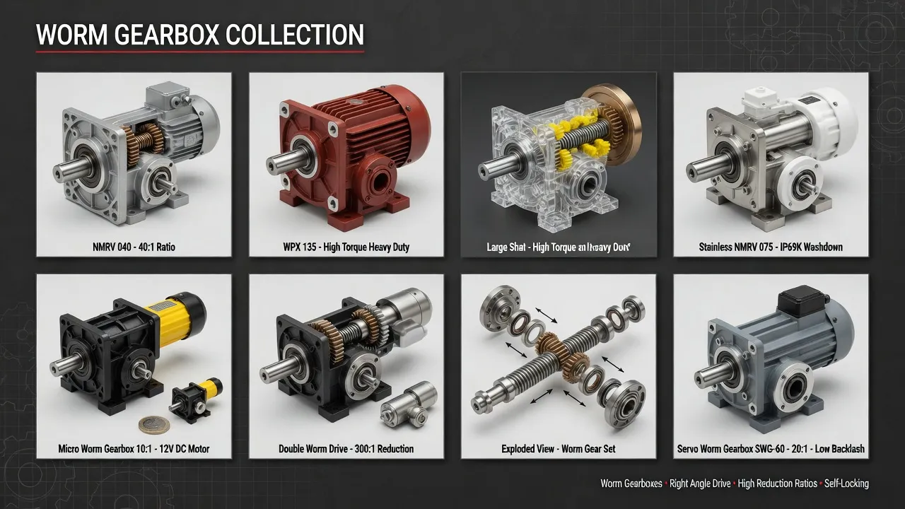
Technical Parameters: Medical Imaging Table Drive Specification Window
The table below summarizes specifications distinguishing medical imaging table drives from generic industrial worm gearbox alternatives. Values reflect AGMA 6034-B92 worm gear power rating combined with medical equipment industry conventions for clinical environment service.
| Parameter | Imaging Table Spec | Generic Industrial |
|---|---|---|
| Positioning accuracy | Below 0.1 mm translation | ±0.5-2 mm typical |
| Backlash specification | Below 30 arcseconds | 15-30 arcminutes |
| Reduction ratio | 50:1 – 100:1 self-locking | 5:1 – 100:1 |
| Sound emission | Below 50 dBA at 1 m | 65-75 dBA typical |
| Output torque (rated) | 25 – 180 Nm | 200 – 4,000 Nm |
| Cycle rate capacity | 1.2 million cycles | 100,000-500,000 typical |
| Chemical resistance | Hospital disinfectant rated | Standard industrial |
| MRI compatibility (when needed) | Non-magnetic materials | Ferrous standard |
The single specification most often miscalculated on medical imaging table projects is the cumulative cycle count for fatigue analysis. Catalog torque ratings assume cycle counts in tens of thousands across the equipment service life — clinical imaging table applications reach 1+ million cycles within the same period. Service factor 2.0 minimum applied to steady-state translation torque covers typical clinical imaging table operations, with the high-cycle requirements driving bearing fatigue calculations and lubrication interval specifications. Drives sized below 2.0 service factor experience progressive accuracy degradation within 3-5 years of clinical service rather than reaching the 10-12 year service life target that justifies medical equipment fleet investment economics.
Application Matrix: Where Medical Imaging Table Drives Operate
CT Scanner Patient Tables
CT scanner patient tables provide longitudinal patient translation through the imaging gantry, with translation strokes typically 1,800-2,200 mm at speeds 30-150 mm/s during scanning operations. Drive specifications include sub-0.1 mm positioning accuracy, output torque 60-120 Nm depending on patient table mechanical advantage, and full hospital chemical compatibility. The CT table operates in non-magnetic environments allowing standard ferrous drive materials. Major CT scanner OEMs deploy these drives across diagnostic imaging departments, oncology radiotherapy planning departments, and emergency department CT installations.
MRI Scanner Patient Tables (MRI Suite Outside Field)
MRI scanner patient table drives mount outside the magnetic field of the MRI magnet, with the patient table extending into the magnet bore through non-magnetic table extension mechanisms. The drive itself can use standard ferrous materials when mounted outside the 5-Gauss line of the magnet — typically requiring drive position 3-5 meters from the magnet center. Output torque requirements range 80-180 Nm reflecting the longer mechanical advantage of the table extension mechanism plus the patient mass loading. Drive specifications include all the precision and clinical compatibility requirements of CT table drives plus careful mounting position verification relative to the MRI magnetic field map.
Radiotherapy Treatment Couches
Linear accelerator radiotherapy treatment couches use precision drives for patient positioning during cancer radiation treatment delivery, with sub-millimeter accuracy requirements matching the tumor targeting precision required for stereotactic body radiation therapy (SBRT) and intensity-modulated radiation therapy (IMRT) treatment delivery. Drive specifications include the precision positioning of CT and MRI table drives plus radiation hardness considerations for service environments adjacent to the linear accelerator radiation source. Output torque requirements range 60-150 Nm for typical treatment couch designs.
Interventional Imaging C-Arm Tables
Interventional imaging suites deploy C-arm fluoroscopy systems with patient tables that provide multi-axis positioning capability supporting cardiac catheterization, neurointerventional procedures, and orthopedic intervention applications. Drive specifications include sub-millimeter positioning accuracy plus rapid response characteristics matching interventional procedure workflow requirements. Output torque requirements vary 25-100 Nm across the multi-axis drive applications. Reference precision drive specifications for interventional imaging table drive sizing.
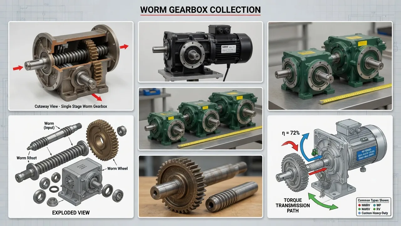
Selection Roadmap: Step-by-Step Workflow
The four-step procedure below covers medical imaging table drive selection from initial requirements documentation through commissioning verification.
Define Positioning Accuracy Budget and Verify Backlash Allocation
Document positioning accuracy requirement (typically below 0.1 mm for diagnostic imaging) and allocate the accuracy budget across servo loop performance, encoder resolution, drive backlash contribution, and mechanical tolerance stack-up. Convert backlash budget from linear units (mm) to angular units (arcseconds) using the drive-to-screw mechanical advantage. Specify backlash class below 30 arcseconds for sub-0.1 mm positioning applications.
Calculate Translation Torque and Verify Self-Locking Holding
Determine output torque from worst-case patient mass × drive-to-screw mechanical advantage, accounting for screw friction and acceleration phases of the translation motion profile. Apply 2.0 service factor for clinical high-cycle service. Verify reduction ratio above 50:1 for self-locking holding capability — important to maintain table position during image acquisition windows without continuous servo loop power application. Self-locking specifications also support fail-safe behavior during emergency power-off events.
Specify Quiet Operation and Chemical-Resistant Finish
Order DIN 3974 quality grade Q5 (premium precision class) tooth geometry for sound emission below 50 dBA at 1 meter distance. Specify chemical-resistant powder coating or stainless steel housing finish compatible with hospital-grade disinfectants (quaternary ammonium compounds, hydrogen peroxide formulations, alcohol-based products). Verify seal materials use Viton fluoroelastomer or EPDM rubber for compatibility with the specific disinfectant chemistry used in the clinical environment.
Document MRI Compatibility and Validation Requirements
For MRI applications verify drive mounting position relative to magnet 5-Gauss line for ferrous material compatibility, or specify non-magnetic drive materials for in-bore mounting applications. Document medical equipment validation requirements including IEC 60601-1 medical electrical equipment safety, IEC 60601-1-2 electromagnetic compatibility, and specific imaging modality standards. Verify factory acceptance test report includes measured backlash, sound emission, and accuracy verification per medical equipment validation protocols.
Spare Parts Integration: Hospital Biomedical Engineering
Hospital biomedical engineering departments prioritize spare drive inventory matching the consequences of imaging equipment outage on diagnostic service capacity — typically every department carries one complete spare drive matched to each imaging system in the equipment fleet, with drive replacement coordinated with scheduled OEM service visits. The precision-ground worm and worm wheel pair reaches 8,000+ operating hours under proper synthetic lubrication and clinical environment protection — typically translating to 10-12 year service life under clinical imaging table service patterns matching the typical scanner economic life.
Premium-grade SKF or NSK precision angular contact ball bearings throughout the drive handle the combined radial and thrust loads typical of medical imaging table service with L10 fatigue life exceeding 8,000 hours under rated load. The bearings undergo individual selection for matched preload to maintain rotational accuracy across the full service life. Viton fluoroelastomer or EPDM rubber seal lips with stainless garter springs maintain ingress protection against hospital-grade disinfectant exposure across the multi-year clinical service period.
Spare parts kits combining matched worm and worm wheel pair, complete bearing set, all shaft seals, gasket and o-ring kit, breather valve, and synthetic lubricant fill provide complete rebuild capability during scheduled medical equipment maintenance windows coordinated with scanner OEM service visits. Akgnx Co., Ltd ships kits with serialized matching documentation for the worm-worm wheel pair, ensuring backlash specification reproducibility across rebuild cycles. All wear components ship from the same factory production runs to ensure dimensional consistency for precision medical equipment rebuilds.

Cost & Sustainability: Total Ownership Across 12-Year Scanner Life
Medical imaging equipment OEMs and hospital operations evaluate patient table drive investments across the scanner economic life — typically 10-12 years matching depreciation schedules for major medical imaging capital investments. The table compares total cost of ownership for medical-grade table drives against generic industrial alternatives across this horizon.
| Cost Component | Medical-Grade VRV | Generic Industrial |
|---|---|---|
| Initial unit price (FOB) | USD 2,800 – 8,500 | USD 750 – 2,800 |
| Service life imaging duty | 10-12 years | 3-5 years |
| Replacement frequency | 1× over 12 years | 2-3× over 12 years |
| Procedure disruption cost | Negligible | USD 1,500-3,500 per event |
| Validation re-test cost | Standard interval | USD 2,500-5,500 per replacement |
| 12-year cumulative TCO | ~ 1.5× installed cost | ~ 7.8× installed cost |
Sustainability and compliance documentation accompanies every medical-grade drive shipment. The housing carries CE marking per EU Machinery Directive 2006/42/EC and complies with RoHS Directive 2011/65/EU. Manufacturing follows ISO 9001:2015 quality management procedures with full material traceability from bronze worm wheel chemical composition through case-hardened worm shaft heat-treatment records. Worm gear tooth geometry follows DIN 3974 quality grade Q5 (premium precision class) with load capacity per AGMA 6034-B92 worm gear power rating methodology adjusted for medical equipment service factor. Documentation supports medical equipment validation per IEC 60601-1 family standards.
Synthetic polyalphaolefin (PAO) lubricant fills support 8,000-hour drain intervals (approximately 4-5 years of clinical operation) producing significantly less waste oil compared to mineral oil alternatives requiring 1,500-hour change intervals. The 10-12 year service life eliminates 1-2 replacement cycles compared to generic industrial alternatives, substantially reducing the equipment lifecycle environmental footprint. Akgnx Co., Ltd manufactures medical-grade imaging table drives through a dedicated medical equipment drive program serving medical imaging equipment OEMs, hospital biomedical engineering departments, and clinical equipment service organizations globally.
Customer Testimonials from Medical Imaging Operations
“Our hospital system operates 14 CT scanners and 9 MRI systems across 4 hospital campuses with approximately 450 daily imaging procedures combined. We standardized on VRV030-based imaging table drives in 2020 after experiencing chronic accuracy degradation on the original drives within 4-5 years of clinical service. Five years into the standardization, we’ve maintained sub-0.1 mm positioning accuracy across the imaging fleet without recalibration events between annual scheduled QA verifications. The accuracy stability supports our ACR accreditation requirements.”
— Director of Biomedical Engineering, Healthcare System, USA Northeast
“As a CT scanner OEM serving the European hospital market, we evaluated multiple alternative table drive suppliers for our diagnostic imaging product line. Akgnx VRV030 medical-grade drives passed our sub-0.1 mm positioning accuracy verification including factory-matched worm-worm wheel backlash specification below 30 arcseconds and sound emission below 48 dBA at 1 meter distance. The serialized matching documentation supports our medical equipment validation per IEC 60601-1 requirements and our hospital customer commissioning processes.”
— Director of Engineering, CT Scanner OEM, Germany
“We retrofitted patient table drives across 6 radiotherapy treatment couches in our cancer center after experiencing accuracy degradation that compromised our SBRT treatment delivery precision targets. The VRV030 replacement drives mounted to existing treatment couch interfaces with coordinated linac OEM service support. Three years into the retrofit program, we’ve maintained sub-0.5 mm patient positioning accuracy across the affected treatment couches, supporting our cancer center’s stereotactic body radiation therapy treatment program clinical commitments.”
— Chief Medical Physicist, Cancer Treatment Center, USA Pennsylvania
“Our interventional radiology suite operates C-arm fluoroscopy systems supporting cardiac catheterization and neurointerventional procedure programs. The VRV030 precision drives we deployed across 4 interventional table positions have completed approximately 800,000 positioning cycles each over 4 years of multi-shift clinical operation with zero accuracy degradation events. The sub-millimeter positioning capability and quiet operation supports our cardiac catheterization lab clinical workflow and patient comfort objectives.”
— Director of Interventional Radiology, Academic Medical Center, USA Boston
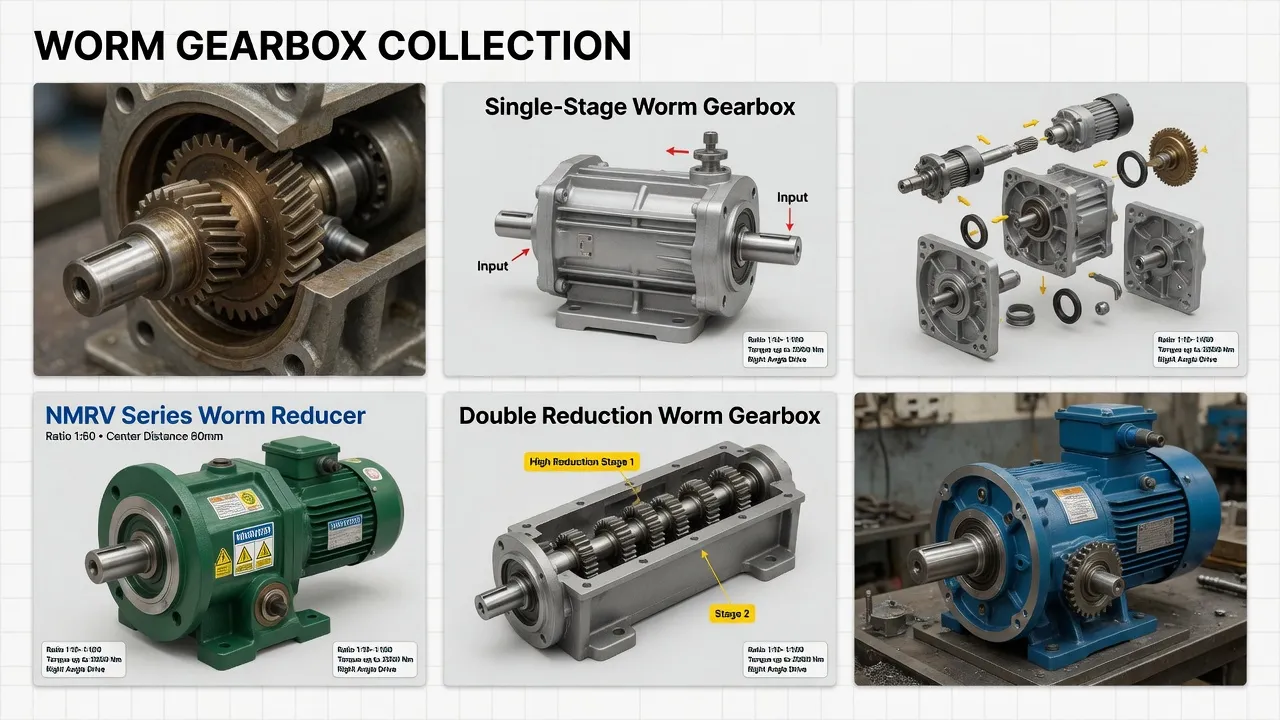
Recommended Drive: VRV030 Precision Worm Gearbox for Medical Imaging Service
For CT scanner patient tables, MRI scanner patient tables (with proper magnetic field positioning), radiotherapy treatment couches, and interventional imaging C-arm tables, the VRV030 Precision Worm Gearbox in medical imaging table specification targets the 10-12-year-service, sub-millimeter-accuracy, clinical-environment service class with engineering features specifically chosen to address the failure modes that retire generic gearbox alternatives within 3-5 years of clinical service.
Specifications include precision-machined cast iron housing with hospital-grade chemical-resistant finish compatible with quaternary ammonium compounds, hydrogen peroxide formulations, and alcohol-based hospital disinfectants, factory-matched precision-ground worm and worm wheel pair (DIN 3974 quality grade Q5 premium precision class) with serialized matching documentation, centrifugally cast tin bronze ZCuSn10P1 worm wheel per ISO 1338 meshing with case-hardened 20CrMnTi steel worm shaft hardened to HRC 58-62 surface, premium-grade angular contact ball bearings rated for 8,000-hour L10 fatigue life under combined radial and thrust loading, fluoroelastomer (Viton) or EPDM rubber double-lip seals with stainless garter springs at all shaft penetrations rated for hospital-grade disinfectant compatibility, IP65 ingress protection plus splash-resistant breather configuration designed for clinical environment exposure, synthetic polyalphaolefin (PAO) lubricant fill rated for 8,000-hour drain intervals, servo motor mounting flange per IEC 72 standard with matched encoder communication protocol options, and stainless steel A2 mounting hardware throughout. Reduction ratios from 50:1 through 100:1 deliver appropriate output speeds for medical imaging table applications. Output torque ratings reach 180 Nm continuous with backlash specification below 30 arcseconds factory-verified per unit. Sound emission below 50 dBA at 1 meter distance verified through factory acceptance test. CE marking, RoHS compliance, ISO 9001:2015 quality system certification, and IEC 60601-1 medical equipment compatibility documentation ship with every unit.
Beyond the VRV030 frame, complete medical imaging table drive packages typically pair the gearbox with high-resolution servo motors with matched absolute encoder feedback, shielded encoder cables rated for medical electromagnetic environment per IEC 60601-1-2, electromagnetic brake assemblies for absolute position holding during image acquisition windows, and full grade 8.8 stainless steel mounting hardware throughout. Akgnx Co., Ltd supplies matched drive packages for medical imaging equipment OEMs and provides aftermarket replacement units for installed clinical imaging fleets across major medical equipment markets globally.
Specifying Drives for Medical Imaging Tables?
Send imaging modality, table envelope, payload mass, accuracy specifications, and clinical environment exposure. We supply VRV030 precision drives engineered for sub-0.1 mm positioning with backlash below 30 arcseconds and hospital-grade chemical compatibility.
Frequently Asked Questions
© Akgnx Co., Ltd · About Us · Contact Us · [email protected]