
A 12-ton industrial winch holding a suspended steel coil 8 meters above a fabrication shop floor relies entirely on its drive train to hold position when operators step away between lift cycles. If the holding mechanism slips even a few millimeters per minute under static load, the coil drifts downward through the shift until the operator returns to find the load resting somewhere unexpected — or worse, on top of equipment that was below the lift path. Industrial winch drive specifications therefore center on one engineering property above all others: the absolute holding capability when the motor is de-energized and any external brake hardware happens to be in a degraded condition. Properly specified worm gearbox winch drives deliver this holding capability through pure gear geometry, with self-locking active whenever the reduction ratio remains above the threshold where the worm thread lead angle falls below the static friction angle of the steel-on-bronze meshing surfaces.
This guide covers the static and dynamic self-locking characteristics that make worm gearboxes the dominant drive choice for industrial winch service, addresses the heavy-duty service factor requirements typical of hoisting applications, walks through selection criteria per AGMA 6034-B92 worm gear power rating methodology, and provides a complete maintenance roadmap for installed winch fleets across construction, marine, mining, and industrial pulling sectors. Audience: winch and hoist OEM engineers, plant rigging supervisors, and procurement specialists sourcing replacement drives for installed lifting equipment.
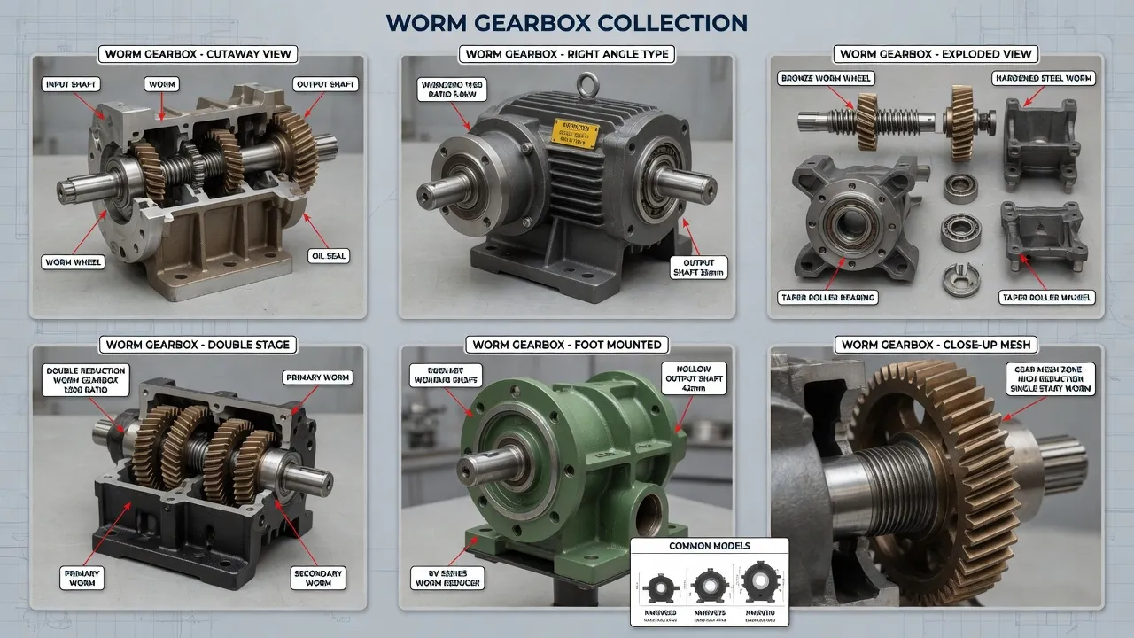
Why Are Industrial Winches So Demanding on Drive Self-Locking?
Winch service combines three operational characteristics that make holding capability the dominant specification consideration. The first is the suspended-load hazard profile — any drive train slip or slow back-driving event puts personnel and equipment below the lift path at direct risk, regardless of whether the slip happens during active operation or during static hold conditions between operator interventions. The second is the cyclical loading pattern that fatigues external brake mechanisms over time: each lift cycle exercises the brake through engagement and release motions, with brake pad wear, hydraulic seal degradation, or electrical contactor failure eventually compromising the redundant safety hardware that supplements the primary drive train. The third is the duty profile combining heavy lift events with extended static hold periods, where the drive train absorbs steady torque without rotation for hours or days while the load remains suspended.
External brake hardware fails in predictable patterns under this duty cycle. Mechanical disc brakes lose pad material across thousands of engagement cycles, eventually reducing static holding torque below the rated value. Hydraulic spring-applied brakes suffer seal degradation that produces gradual hydraulic pressure loss with the load suspended, even when the system passes routine inspection. Electromagnetic brakes depend on coil integrity and air gap precision that drift over years of thermal cycling. The self-locking worm gearbox built into the primary drive eliminates dependence on these wear-prone auxiliary mechanisms by exploiting the geometric property of high-ratio worm meshing: the bronze worm wheel cannot back-drive the steel worm shaft when the lead angle falls below approximately 5.7°, regardless of applied load magnitude or duration.
How Does Worm Self-Locking Differ from External Brake Mechanisms?
Static Self-Locking vs Dynamic Self-Locking
Worm gear self-locking actually exists in two distinct forms with different engineering implications. Static self-locking activates when the load is stationary and remains at zero rotation — the worm wheel cannot initiate back-driving from rest because static friction at the lead angle exceeds the back-driving force component. This static self-locking activates reliably at reduction ratios above 30:1, where the lead angle stays below 5.7° for typical bronze-on-steel meshing per worm gear lead angle calculations. Dynamic self-locking, by contrast, requires reduction ratios above approximately 45:1 — the kinetic friction coefficient is lower than static friction, so a worm wheel that is already rotating may continue to rotate under back-driving forces even at ratios where static locking would activate.
Why Winch Service Specifies Static Plus External Brake
Industrial winch design typically combines worm gearbox static self-locking with an external brake mechanism for redundancy rather than relying on either alone. The reasoning: static self-locking holds the load absolutely after lift cycles complete, eliminating slow drift during extended hold periods. The external brake provides dynamic stopping capability during powered lowering operations and serves as redundant safety hardware in case primary drive train damage compromises the worm self-locking action. Some heavy-duty hoist applications rely on dynamic self-locking at high reduction ratios (60:1 and above) to provide controlled descent rates during powered lowering — but the redundant external brake remains good engineering practice regardless of dynamic self-locking design.
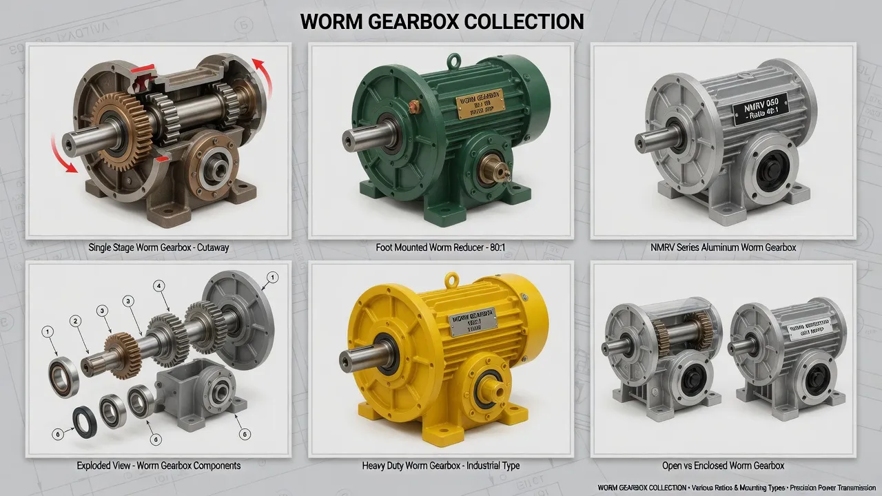
Technical Parameters: Industrial Winch Specification Window
The table below summarizes specifications distinguishing winch-grade worm gearbox configurations from generic industrial alternatives. Values reflect AGMA 6034-B92 worm gear power rating methodology combined with hoisting equipment industry conventions for service factor and holding torque margin.
| Parameter | Winch Specification | Generic Industrial |
|---|---|---|
| Output configuration | 90° hollow shaft on drum shaft | 90° solid shaft typical |
| Reduction ratio range | 40:1 to 100:1 (within self-lock zone) | 5:1 to 100:1 |
| Output torque (rated) | 800 – 18,000 Nm | 200 – 2,000 Nm typical |
| Static self-locking torque | 120 – 1,400 Nm at 60:1+ | 25 – 280 Nm typical |
| Service factor (hoist duty) | 2.5 minimum, 3.0 recommended | 1.0 – 1.25 typical |
| Operating temperature | -20 °C to +90 °C | -10 °C to +60 °C |
| Sealing rating | IP66 outdoor service | IP54 standard |
| Compliance | CE, RoHS, ISO 9001:2015 | CE only |
The single specification most often miscalculated on industrial winch projects is the service factor. Catalog torque ratings assume uniform load with three or fewer starts per hour and minimal shock loading — conditions virtually no real winch meets. Lift cycles include startup acceleration shock, occasional snatch loading from sudden load contact, and the cyclic stop-start pattern of repetitive lift operations. Service factor 2.5 minimum covers general industrial hoist duty, with severe applications such as snatch-pull recovery winches or marine hauling justifying 3.0 to 3.5. Skipping this adjustment produces gearboxes that fail within 12 to 24 months of winch service regardless of other specifications.
Application Matrix: Where Industrial Winch Drives Operate
Construction Site Material Hoists
Construction sites deploy electric winches to lift building materials, steel beams, formwork panels, and equipment between ground level and active work floors. Lift heights range from 8 meters on small commercial projects to 60+ meters on high-rise construction. Drive duty combines frequent lift cycles during active hours with extended idle periods overnight when full loads remain suspended in temporary positions. Output torques on these drives reach 1,500 to 8,000 Nm depending on lift capacity (typically 500 kg to 5,000 kg) and drum diameter. Self-locking eliminates the safety risk of drift during overnight hold periods, supporting responsible construction site practice across multi-month project schedules.
Marine Anchor Windlasses and Mooring Winches
Marine vessels deploy anchor windlasses and mooring winches to manage anchor chains and dock lines. Anchor windlass duty handles loads from 2 to 15 tons of anchor plus chain weight, with shock loading from wave action transmitted up the anchor chain into the drive. Mooring winches manage continuous tensioning duty maintaining vessel position against tide and wind forces. Both applications combine heavy load capacity with marine environment exposure (salt spray, washdown service) demanding upgraded sealing and corrosion-resistant materials. Output torques range 2,000 to 12,000 Nm. Service factor 3.0 covers the snatch-load shock from wave-induced anchor chain tensioning events.
Mining and Underground Hoisting
Mining operations use winches for personnel transport in shaft cages, material hoisting from underground workings, and equipment positioning during stope development. Personnel hoists carry stringent regulatory requirements for redundant fail-safe operation that drive multi-stage drive train specifications. Material hoists handle ore weights up to 10 tons per cycle. Equipment positioning winches support drilling rigs, longwall shearer installations, and mine development equipment. Output torques range 3,500 to 18,000 Nm depending on application. Self-locking provides primary anti-runback protection that supplements regulatory-mandated external brake systems.
Industrial Pulling and Towing Winches
Industrial pulling winches handle line haul applications including shipyard ship positioning, railroad car movement, oil rig pipe pulling, and underground cable installation. The duty combines high pull force requirements with the need to hold positioned loads against tension during operational pauses. Output torques on heavy pulling winches reach 5,000 to 18,000 Nm. Self-locking holds positioned loads absolutely without continuous motor torque, reducing energy consumption during extended operational pauses while eliminating the safety risk of load drift. Refer to industrial reducer load capacity references for detailed application sizing examples.
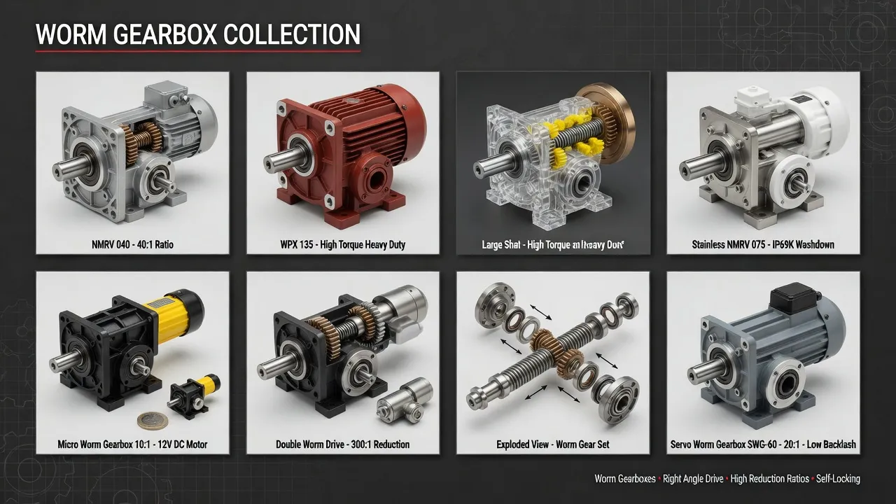
Selection Roadmap: Step-by-Step Workflow
The four-step procedure below covers industrial winch drive selection from initial requirements documentation through commissioning verification.
1
Calculate Lift Pull Force and Drum Torque
Determine maximum line pull from rated lift capacity × wire rope reeving factor + acceleration force during startup. Convert line pull to drum shaft torque using drum diameter (full drum vs empty drum produces different torque values — design for the worst case). Document worst-case startup torque (typically 1.5 to 2.0× steady-state) for service factor sizing. Lifts involving load swing or pendulum motion add transient peak loads that must be incorporated into the design torque.
2
Apply Service Factor 2.5 Minimum for Hoist Duty
Multiply calculated steady-state torque by 2.5 for general industrial hoist service, 3.0 for marine winches with wave-induced shock loading, and 3.5 for snatch-pull recovery and similar shock-prone applications. The resulting equivalent uniform-duty torque is what the catalog rating must exceed at the chosen reduction ratio. Service factor below 2.5 produces winch drives that fatigue prematurely from cyclic shock loading inherent to hoisting operations.
3
Select Reduction Ratio for Static Self-Locking
Choose a reduction ratio of 40:1 minimum to ensure static self-locking activates reliably across the full load range, with 60:1 preferred for personnel hoist applications and high-consequence loads. For target lift speeds requiring lower primary ratios, specify a helical primary reduction stage paired with a high-ratio worm secondary stage. Verify the lead angle calculation appears on the gearbox specification documentation along with the rated static self-locking torque value.
4
Specify IP66 Sealing for Outdoor or Marine Service
Confirm the gearbox sealing package includes IP66 ingress protection for outdoor construction service, or IP66 plus marine-grade epoxy paint for waterfront and marine applications. Specify Viton seal lips at all shaft penetrations for chemical resistance to lubricant oxidation byproducts. Use stainless steel A2 or A4 mounting hardware throughout to prevent galvanic corrosion seizing during future maintenance, particularly in salt spray environments.
Spare Parts Integration: Winch Fleet Maintenance
Industrial winch maintenance prioritizes replacement stock matching project schedules and seasonal operating cycles. The worm shaft, machined from 20CrMnTi case-hardened steel with ground and polished thread surfaces hardened to HRC 58-62 per DIN 3974 quality grade Q8, reaches 30,000+ operating hours under proper lubrication. Worm shaft replacement is needed only after major rebuild events. The worm wheel, centrifugally cast from premium tin bronze ZCuSn10P1 per ISO 1338 with ground tooth surfaces, is the higher-cycle wear component — replacement intervals run 20,000 to 30,000 hours depending on lift cycle frequency and shock loading severity. For detailed material specifications see worm and gear set technical references.
Premium-grade SKF or NSK tapered roller bearings on the worm shaft handle the combined radial and axial loads typical of winch service. L10 bearing fatigue life under rated continuous duty exceeds 25,000 hours, with bearing replacement typically performed concurrent with worm wheel service rather than as a separate maintenance event. Output and input shaft seals (Viton with stainless garter springs) require preventive replacement at 4-year intervals or whenever evidence of moisture intrusion appears in the lubricant sample.
Spare parts kits combining worm shaft, worm wheel, complete bearing set, all shaft seals, gasket kit, and breather valve provide complete rebuild capability for installed winch fleets. Akgnx Co., Ltd ships kits packaged for typical construction site, marine operations, and mining maintenance shop inventory practices, with all wear components sourced from the same factory production runs to ensure dimensional consistency across the rebuild cycle.
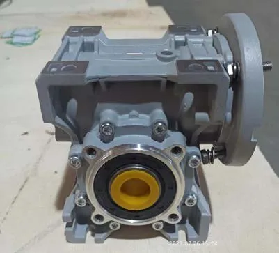
Cost & Sustainability: Total Ownership Across 10-Year Service
Construction equipment fleet operators evaluate winch investments across 8 to 10 year horizons matching equipment depreciation schedules. The table compares total cost of ownership for winch-grade specialized worm gearboxes against generic industrial alternatives across this horizon.
| Cost Component | Winch-Grade MRV | Generic Industrial |
|---|---|---|
| Initial unit price (FOB) | USD 580 – 2,400 | USD 380 – 1,400 |
| Replacement frequency | 1× over 10 years | 3× over 10 years |
| External brake supplement | Reduced spec (redundancy only) | Full spec required |
| Lubricant interval | 5,000 hours / 24 months | 2,000 hours / 8 months |
| Drift incident liability | Eliminated (self-lock) | Brake failure mode |
| 10-year cumulative TCO | ~ 1× installed cost | ~ 3.0× installed cost |
Sustainability and compliance documentation accompanies every winch-grade MRV gearbox shipment. The housing carries CE marking per EU Machinery Directive 2006/42/EC and complies with RoHS Directive 2011/65/EU restricting hazardous substances. Manufacturing follows ISO 9001:2015 quality management procedures with full material traceability from bronze worm wheel chemical composition through case-hardened worm shaft heat-treatment records. Worm gear tooth geometry follows DIN 3974 quality grade Q8 with load capacity per AGMA 6034-B92 worm gear power rating methodology adjusted for hoist service factor.
Synthetic polyalphaolefin (PAO) lubricant fill produces 65 to 75 percent less waste oil over the equipment service life compared to mineral oil alternatives requiring more frequent changes — biodegradability per OECD 301 standards in spillage concentrations. Akgnx Co., Ltd manufactures winch-grade worm gearboxes through a dedicated heavy-duty hoisting drive program serving construction, marine, mining, and industrial pulling customers across major industrial regions globally.
Customer Testimonials from Winch and Hoist Operators
“Our construction equipment fleet runs 28 material hoists across active projects. We replaced the original drive packages with self-locking MRV units after losing a 2-ton hoist load during a 2023 brake failure event — repair cost USD 45,000 plus the safety review consequences. 18 months in, zero drift events and we relaxed our quarterly brake inspection schedule to align with the gearbox annual service cycle.”
— Equipment Maintenance Director, Construction Group, Saudi Arabia
“As a marine windlass OEM serving the offshore service vessel market, we evaluated four alternative gearbox suppliers for our standard 8-ton anchor windlass package. MRV passed our 2,000-cycle wave-induced shock load test with measured backlash growth under 0.05° — significantly better than competing alternatives. Akgnx held our annual production schedule across two consecutive years with consistent quality.”
— Director of Engineering, Marine Deck Equipment OEM, Norway
“We sourced direct dimensional replacements for an installed fleet of 12 underground mining material hoists. The MRV mounted to existing brackets without modification and supported our updated mine safety review documentation requirements with documented self-locking specifications. Documentation arrived complete with the first shipment including AGMA calculation summary.”
— Plant Engineering Manager, Underground Mining Operation, South Africa
“Industrial pulling winches at our shipyard handle 40-meter line haul positioning loads up to 10 tons. The original drive packages required brake servicing every 90 days due to the heavy duty cycle. The MRV replacement extended brake service intervals to 18 months because the worm self-locking carries the static hold load between operational pulls. Significant maintenance budget impact across our 14-winch installation.”
— Operations Manager, Shipyard Operations, Republic of Korea
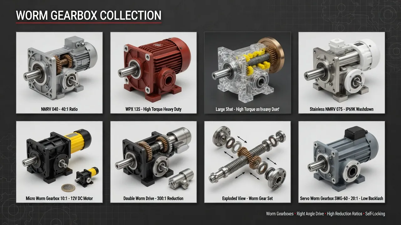
Recommended Drive: MRV NMRV Standard Worm Gearbox for Industrial Winches
For industrial winch applications across construction, marine, mining, and industrial pulling sectors, the MRV NMRV Standard Worm Gearbox Series targets the self-locking, heavy-duty service class with engineering features specifically chosen to address the failure modes that retire general industrial alternatives within hoist fleet operating cycles.
Specifications include cast iron housing with two-coat industrial epoxy paint for outdoor and marine corrosion resistance, centrifugally cast tin bronze ZCuSn10P1 worm wheel meshing with case-hardened 20CrMnTi steel worm shaft per DIN 3974 quality grade Q8, fluoroelastomer (Viton) double-lip seals with stainless garter springs, and IP66 ingress protection. Reduction ratios from 40:1 through 100:1 maintain reliable static self-locking across the full duty range. Output torque on the MRV150 frame reaches 6,800 Nm continuous with self-locking holding torque to 1,400 Nm at 80:1 reduction. CE marking, RoHS compliance, and ISO 9001:2015 quality system certification ship with every unit.
Beyond the MRV frame, complete winch drive packages typically pair the worm gearbox with IEC TEFC three-phase induction motors at appropriate frame size, electromagnetic spring-applied brakes for redundancy on personnel hoist applications, and stainless steel mounting hardware throughout marine installations. Akgnx Co., Ltd supplies matched drive packages for winch and hoist OEMs and provides aftermarket replacement units for installed equipment fleets across major industrial regions globally.
Specifying Drives for Industrial Winches?
Send rated lift capacity, drum diameter, lift cycle frequency, and required output torque. We supply MRV NMRV Standard Worm Gearboxes engineered for self-locking heavy-duty hoist service.
Frequently Asked Questions
© Akgnx Co., Ltd · About Us · Contact Us · [email protected]