
A 35-meter inclined belt conveyor transporting 180 tons of crushed limestone per hour up a 16° incline carries roughly 2,800 kg of material between the head and tail pulleys at any moment. When facility power drops without warning, that loaded belt becomes a runaway gravity hazard within fractions of a second — the entire material column slides backward, the belt whips off the head pulley, and the cleanup operation typically costs USD 18,000 to 35,000 in labor, replacement belt sections, and lost production hours. Properly specified worm gearbox drives eliminate this failure mode through pure mechanical geometry, holding the loaded belt absolutely without any backstop component, electromagnetic brake, or external safety device. Inclined conveyor designers have leaned on this property for over six decades, and the engineering reasoning still holds against every modern alternative drive technology evaluated for the same duty.
This guide walks through the self-locking principle behind worm gearbox anti-reversal protection, lays out the right-angle drive configuration that fits behind conveyor head pulleys in space-constrained installations, addresses selection criteria per AGMA 6034-B92 worm gear power rating methodology, and provides a complete maintenance roadmap for installed conveyor fleets. Audience: conveyor system OEM engineers, plant maintenance managers, and procurement specialists sourcing replacement drives for material handling installations across mining, aggregate, and bulk goods sectors.
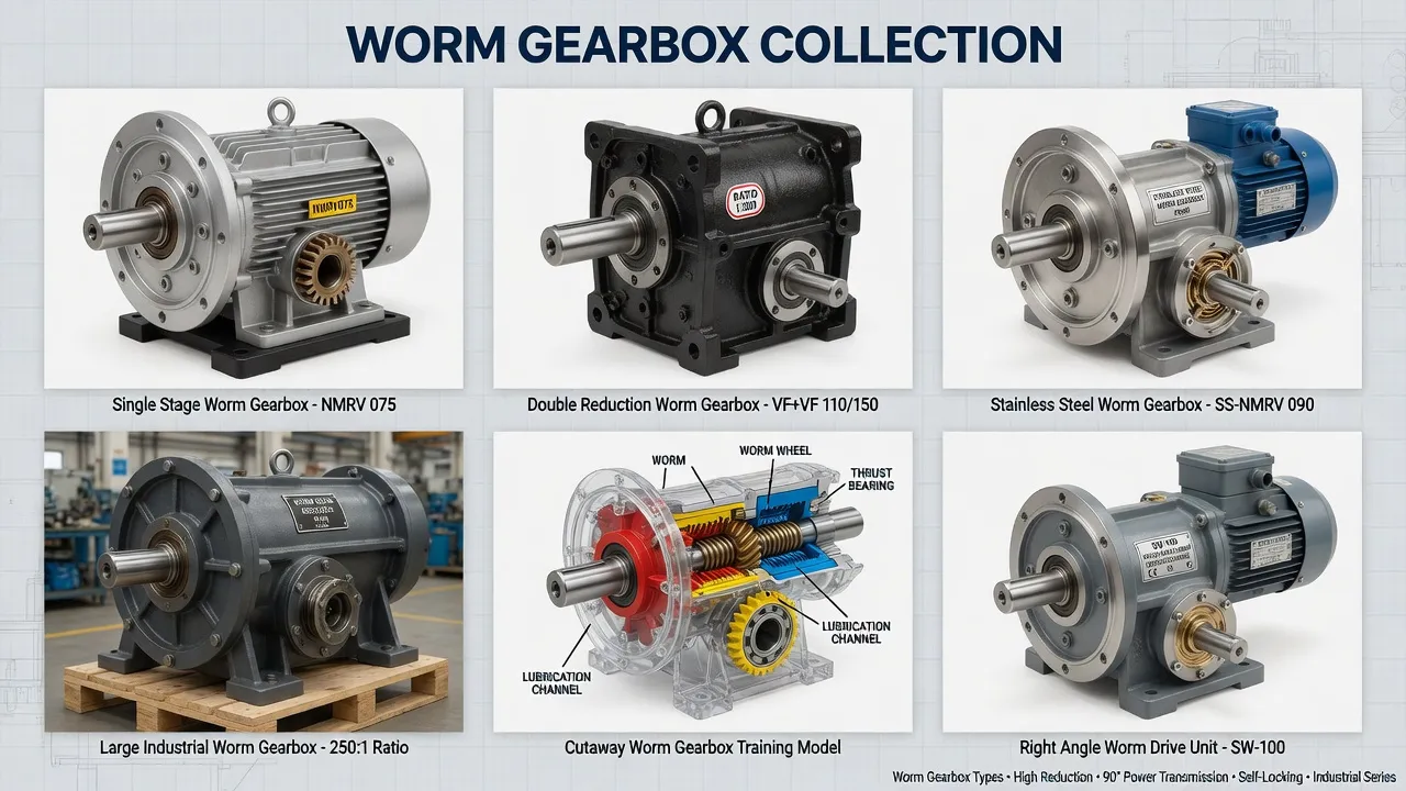
Why Does Inclined Conveyor Belt Reversal Matter So Much?
Belt reversal during a power-loss event creates three cascading failure modes that compound rapidly. The first is mechanical damage to the belt itself — sudden reversal under full load whips the belt off the head pulley snub roller, fractures the belt splice, and tears the carcass at the loading zone where material was just deposited. The second is structural damage to the conveyor frame as kinetic energy from the runaway material column transfers into the support structure at points the structure was never designed to absorb. The third is the safety hazard to personnel — operators and maintenance technicians working near the conveyor experience sudden uncontrolled motion of equipment they assumed was de-energized.
External backstop devices — wedge clutches, sprag clutches, ratchet-and-pawl mechanisms — address the reversal risk but introduce their own failure modes. Backstops require periodic inspection, lubrication, and eventual replacement. They occupy space behind the head pulley that already runs tight on inclined conveyors. They add capital cost, installation labor, and ongoing maintenance burden. The self-locking worm gearbox built into the primary drive eliminates the need for any of this auxiliary hardware by exploiting the geometric property of high-ratio worm gear meshing: the worm wheel cannot back-drive the worm shaft when the lead angle falls below the friction angle of the meshing surfaces.
How Does Worm Gear Self-Locking Actually Work?
The Geometric Condition for Static Self-Locking
Worm gear self-locking depends on the lead angle of the worm thread relative to the friction angle of the meshing surfaces. When the lead angle falls below approximately 5° to 7° — corresponding to reduction ratios above roughly 30:1 — the bronze worm wheel cannot back-drive the steel worm shaft regardless of applied output torque. The mechanical reasoning: torque applied to the worm wheel produces an axial force component on the worm thread, but if the lead angle is shallower than the friction angle (typically 5.7° for steel-on-bronze with proper lubrication per DIN 3974), the static friction force exceeds the back-driving force component and the system locks geometrically. No external power, no electromagnetic actuation, no ratchet mechanism — the locking is inherent to the mesh geometry.
Why 90° Right-Angle Output Solves Conveyor Mounting
Inclined conveyor head pulleys sit at the end of the conveyor frame with the drive motor typically mounted along the frame side. The 90° right-angle output configuration of worm gearboxes routes motor torque through the housing and out perpendicular to the input — directly aligned with the head pulley shaft. The hollow output shaft option mounts the gearbox directly onto the head pulley shaft, eliminating couplings, alignment surfaces, and the additional sealing points that any inline drive arrangement would require. This compact configuration matters most on conveyors mounted in tight tunnels or behind production line equipment where chassis depth determines installation feasibility.
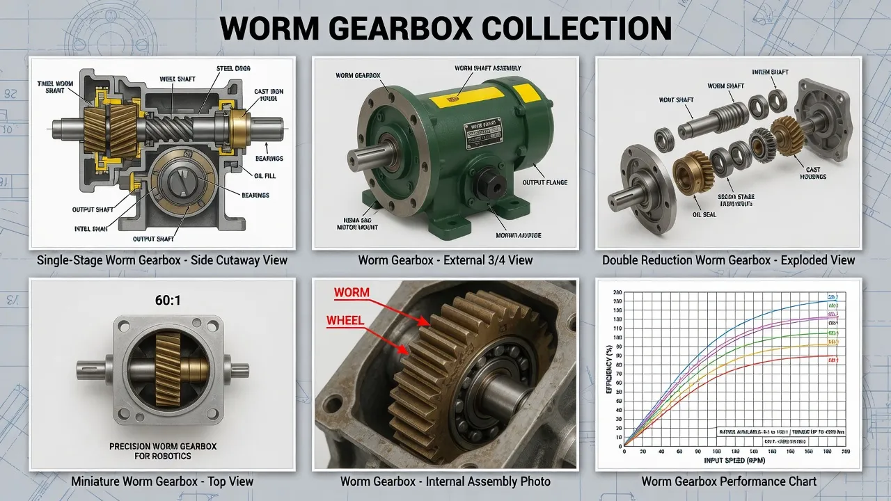
Technical Parameters: Inclined Conveyor Specification Window
The table below summarizes the parameter window distinguishing conveyor-grade worm gearbox specifications from generic catalog selections. Values reflect AGMA 6034-B92 power rating combined with material handling industry conventions for shock loading and continuous duty.
| Parameter | Conveyor Specification | Generic Industrial |
|---|---|---|
| Output configuration | 90° right-angle, hollow shaft | 90° right-angle |
| Reduction ratio range | 5:1 to 100:1 | 5:1 to 100:1 |
| Self-locking ratio threshold | ≥ 30:1 (lead angle < 5.7°) | ≥ 30:1 |
| Self-locking holding torque | 25 – 850 Nm typical | 25 – 850 Nm typical |
| Service factor (lumpy material) | 1.75 minimum | 1.0 – 1.25 typical |
| Operating temperature | -10 °C to +90 °C | -10 °C to +60 °C |
| Sealing rating | IP65 with dust deflectors | IP54 standard |
| Compliance | CE, RoHS, ISO 9001:2015 | CE only |
The single specification most often miscalculated on conveyor projects is the service factor. Catalog torque ratings assume uniform load with three or fewer starts per hour — conditions almost no real conveyor meets. Inclined belt conveyors handling lumpy material with frequent jam-clear restarts require service factor 1.75 minimum, with severe-duty applications justifying 2.0 to 2.5. Multiplying the calculated steady-state torque by the proper service factor produces an equivalent uniform-duty torque that the catalog rating must exceed at the chosen reduction ratio. Skipping this adjustment is the single largest source of premature gearbox failure in conveyor applications.
Application Matrix: Where Inclined Conveyor Drives Operate
Aggregate and Mining Material Handling
Aggregate quarries and mining operations deploy inclined belt conveyors to lift crushed stone, sand, gravel, ore, and processed materials from extraction zones up to processing plants or stockpile yards. Incline angles range from 8° to 22° depending on belt friction characteristics and material angle of repose. Output torques on these drives reach 1,500 to 12,000 Nm depending on belt width (typically 600 to 1,800 mm) and lift height (typically 8 to 35 meters). Self-locking holds the loaded belt during scheduled outages, weather-related shutdowns, or unexpected power events without requiring external backstops that would add maintenance burden in dust-contaminated environments.
Cement and Bulk Material Plants
Cement production lines route raw materials from quarry through crusher, grinding mill, kiln, and finishing operations through dozens of inclined conveyor positions. Each conveyor handles dust-contaminated material at temperatures sometimes exceeding 60 °C ambient near kiln zones. Worm gearbox drives in this service combine self-locking anti-reversal protection with IP65 sealing and synthetic high-temperature lubricant fills. Output torques run 800 to 8,500 Nm depending on conveyor capacity. Service factor 2.0 covers the cyclic loading from material flow surges and the occasional restart against compacted material in the loading zone.
Grain and Agricultural Bulk Storage
Grain elevators, oilseed processing plants, and agricultural bulk storage facilities route product through inclined belt conveyors between receiving pits, storage silos, and shipping loadout. The service combines outdoor weather exposure with continuous-duty operation during harvest seasons running 16 to 24 hours daily. Inclined drives at moderate angles (typically 10° to 18°) carry product weights from 30 to 250 tons per hour, with output torques ranging 400 to 4,500 Nm. Self-locking protects against grain backflow during scheduled maintenance windows or weather-related shutdowns that interrupt production cycles.
Recycling and Solid Waste Handling
Material recovery facilities and waste processing plants deploy inclined conveyors to elevate mixed waste streams between sorting stages. The service combines moderate to severe shock loading from oversized debris with abrasive contamination from the mixed material composition. Worm gearbox drives at service factor 2.5 handle this duty class, with the bronze worm wheel material absorbing shock loads better than rolling-contact gear alternatives. Output torques run 600 to 6,000 Nm depending on belt width and material density.
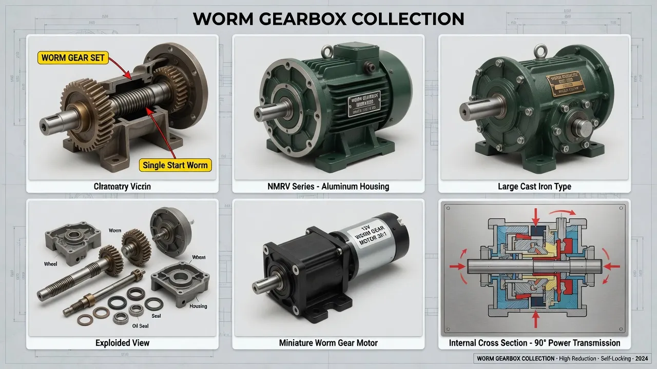
Selection Roadmap: Step-by-Step Workflow
The four-step procedure below covers inclined conveyor drive selection from initial requirements documentation through commissioning verification. Following this sequence produces drives that meet their service life expectations rather than failing within the equipment warranty period.
Calculate Belt Pull Force and Drive Torque
Determine belt pull force from material weight per unit length, incline angle, belt friction coefficient, and acceleration during startup. Convert belt pull to head pulley torque using pulley diameter. Verify the result against the calculated power requirement at target belt speed. Document worst-case startup torque (typically 1.5 to 2.0× steady-state) for service factor sizing.
Apply Service Factor 1.75 Minimum for Lumpy Material
Multiply calculated steady-state torque by 1.75 for typical aggregate handling, 2.0 for severe shock loading from oversized debris or restart-against-compacted-material conditions, and 2.5 for recycling and waste processing where unpredictable solids contact the loading zone. The resulting equivalent uniform-duty torque is what the catalog rating must exceed at the chosen reduction ratio.
Verify Self-Locking Requires Reduction Ratio ≥ 30:1
Geometric self-locking activates only when the worm lead angle falls below approximately 5.7°, which corresponds to single-stage reduction ratios above 30:1. For belt speed requirements that would produce ratios below 30:1, specify a primary helical reducer ahead of the worm gearbox to deliver target output speed while maintaining the high-ratio worm stage that produces self-locking. Verify the lead angle calculation appears on the gearbox specification documentation.
Specify IP65 Sealing with Dust Deflectors
Conveyor drives operate in dust-contaminated atmospheres regardless of the specific industry. Order the gearbox with IP65 ingress protection plus mechanical dust deflectors at all shaft penetrations. Specify Viton seal lips for chemical resistance to lubricant oxidation byproducts across multi-decade service. Use stainless steel A2 or A4 mounting hardware throughout to prevent galvanic corrosion seizing during future maintenance.
Spare Parts Integration: Wear Components for Conveyor Fleets
Conveyor fleet maintenance prioritizes replacement stock for the components that wear under daily duty cycling and dust exposure. The worm shaft, machined from 20CrMnTi case-hardened steel with ground and polished thread surfaces hardened to HRC 58-62 per DIN 3974 quality grade Q8, reaches 30,000+ operating hours under proper lubrication. Worm shaft replacement is needed only after major overhaul events. The worm wheel, centrifugally cast from tin bronze ZCuSn10P1 per ISO 1338 with ground tooth surfaces, is the higher-cycle wear item — replacement intervals typically run 20,000 to 30,000 hours depending on lumpy material exposure and lubricant condition.
Bearings on conveyor-grade frames use SKF or NSK premium tapered roller bearings on the worm shaft for thrust capacity plus deep-groove ball bearings on the worm wheel shaft for radial support. L10 bearing fatigue life under rated continuous duty exceeds 25,000 hours, with bearing replacement typically performed concurrent with worm wheel service rather than as a separate maintenance event. Output and input shaft seals (Viton with stainless garter springs) require preventive replacement at 4-year intervals or whenever evidence of dust intrusion appears in the lubricant sample.
Spare parts kits combining worm shaft, worm wheel, complete bearing set, all shaft seals, gasket kit, and breather valve provide complete rebuild capability for installed conveyor fleets. Akgnx Co., Ltd ships kits packaged for typical mining and aggregate plant maintenance shop inventory practices, with all wear components sourced from the same factory production runs to ensure dimensional consistency across the rebuild cycle.
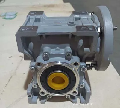
Cost & Sustainability: Total Ownership Across 10-Year Conveyor Service
Mining and aggregate plant operators evaluate equipment investments across 10-year operating horizons because plant capital cycles align with extraction lease terms. The table compares total cost of ownership for conveyor-grade specialized worm gearboxes against generic industrial alternatives across this horizon.
| Cost Component | Conveyor-Grade MRV | Generic Industrial |
|---|---|---|
| Initial unit price (FOB) | USD 380 – 720 | USD 240 – 420 |
| External backstop cost | Eliminated (self-locking) | USD 280 – 850 added |
| Replacement frequency | 1× over 10 years | 3 – 4× over 10 years |
| Lubricant change interval | 6,000 hours / 24 months | 2,000 hours / 8 months |
| Belt damage from reversal | Eliminated | Risk if backstop fails |
| 10-year cumulative TCO | ~ 1× installed cost | ~ 3.2× installed cost |
Sustainability and compliance documentation accompanies every conveyor-grade MRV gearbox shipment. The housing carries CE marking per EU Machinery Directive 2006/42/EC and complies with RoHS Directive 2011/65/EU restricting hazardous substances. Manufacturing follows ISO 9001:2015 quality management procedures with full material traceability from bronze worm wheel chemical composition through case-hardened worm shaft heat-treatment records. Worm gear tooth geometry follows DIN 3974 quality standards with load capacity per AGMA 6034-B92 worm gear power rating methodology.
Synthetic polyalphaolefin (PAO) lubricant fill produces 65 to 75 percent less waste oil over the equipment service life compared to mineral oil alternatives requiring more frequent changes. Akgnx Co., Ltd manufactures conveyor-grade worm gearboxes under a 22-year material handling drive program serving aggregate, mining, cement, and bulk goods customers across European, North American, and Asian markets.
Customer Testimonials from Conveyor Operators
“We replaced 24 inclined conveyor drives across two aggregate quarries with self-locking MRV gearboxes after losing a belt during a thunderstorm power outage in 2023. Cleanup ran USD 28,000 plus four production days. Eighteen months into the new drive installation, zero reversal events and we eliminated the external backstop maintenance line from our annual budget.”
— Maintenance Director, Aggregate Mining Operation, Pennsylvania USA
“Our cement plant runs 38 inclined conveyor positions across the raw material handling and finishing circuits. Akgnx supplied direct dimensional replacements for the original 1990s drive equipment with documented self-locking specifications meeting our updated safety review requirements. Documentation arrived complete with the first shipment including DIN 3974 quality grade verification.”
— Plant Engineering Manager, Cement Production Group, Spain
“As a conveyor system OEM serving the recycling industry, we evaluated five alternative gearbox suppliers for our standard inclined drive package. MRV passed our 2,000-hour shock load test simulating mixed waste handling with measured backlash growth under 0.06°. Akgnx held our annual production schedule across two consecutive years of supply with consistent batch-to-batch quality.”
— Director of Engineering, Material Recovery Equipment OEM, Germany
“Grain elevator inclined conveyor drives at our facility face heavy seasonal duty during 8-week harvest windows running 18 to 22 hours daily. The MRV self-locking eliminates the safety concern of belt reversal during overnight production stops with full belt loads. Zero unscheduled gearbox replacements across three harvest seasons since installation.”
— Operations Manager, Grain Storage Cooperative, Brazil
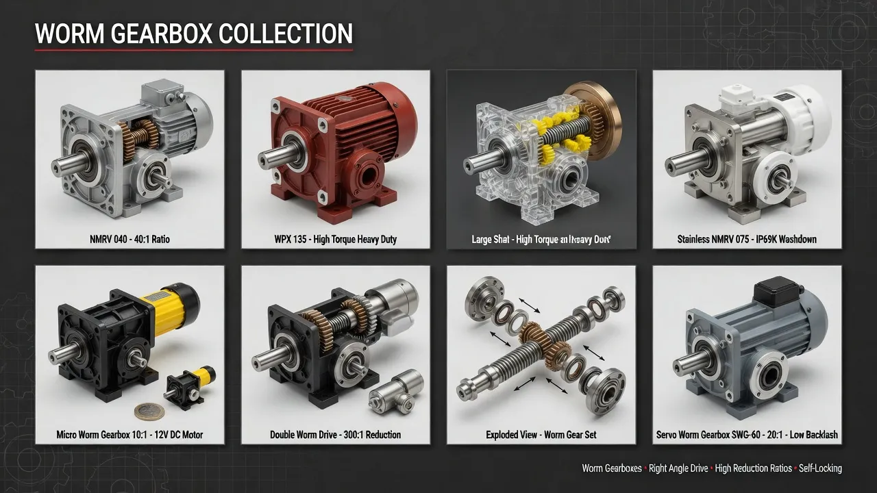
Recommended Drive: MRV Worm Gearbox for Inclined Conveyors
For inclined belt conveyor applications across aggregate, mining, cement, grain handling, and recycling sectors, the MRV worm gearbox targets the self-locking, dust-resistant, shock-tolerant service class with engineering features specifically chosen to address the failure modes that retire general industrial alternatives within conveyor fleet operating cycles.
Specifications include cast iron housing with two-coat industrial epoxy paint for corrosion resistance, centrifugally cast tin bronze ZCuSn10P1 worm wheel meshing with case-hardened 20CrMnTi steel worm shaft per DIN 3974 quality grade Q8, fluoroelastomer (Viton) double-lip seals with stainless garter springs and mechanical dust deflectors, and IP65 ingress protection. Reduction ratios from 7.5:1 through 100:1 cover the full range of inclined conveyor speed and torque requirements. Output torque on the MRV150 frame reaches 3,200 Nm continuous with self-locking holding torque to 850 Nm at 60:1 reduction. CE marking, RoHS compliance, and ISO 9001:2015 quality system certification ship with every unit.
Beyond the MRV frame, complete inclined conveyor drive packages typically pair the worm gearbox with IEC TEFC three-phase induction motors at appropriate frame size, heavy-series roller chain or shaft-mount couplings for any final drive reduction, and elastomeric shock-isolation couplings between motor and gearbox. Akgnx Co., Ltd supplies matched drive packages for conveyor system OEMs and provides aftermarket replacement units for installed equipment fleets across major bulk material handling regions globally.
Specifying Drives for Inclined Belt Conveyors?
Send belt width, lift height, material specification, and required output torque. We supply MRV worm gearboxes with self-locking anti-reversal protection engineered for material handling service.
Frequently Asked Questions
© Akgnx Co., Ltd · About Us · Contact Us · [email protected]