
A 50 MW parabolic trough concentrating solar power (CSP) plant in a desert solar resource region deploys roughly 800 to 1,200 solar collector assemblies, each 100 to 150 meters long, that must continuously track the sun’s azimuth across the daily sky path with pointing accuracy below 0.1° to maintain optical concentration onto the receiver tube running along the focal line of each parabolic mirror trough. Pointing accuracy errors above this threshold cause the focused solar flux to drift off the receiver tube, dropping thermal collection efficiency by approximately 2 percent per 1° of pointing error and producing localized overheating on receiver tube glass envelopes that accelerates failure rates. Each tracking drive operates in desert site conditions where ambient temperatures range -10°C winter mornings to +50°C summer afternoons, where the heat transfer fluid (typically thermal oil or molten salt) reaches 290°C to 565°C during operating cycles, and where dust loading from periodic sandstorms accumulates on every exposed component. Drive failure during operation places the affected collector loop into out-of-focus condition that not only loses thermal output but risks damaging the receiver tube from uncontrolled solar flux pattern. Properly specified parabolic trough tracking drive equipment — built around precision worm gearbox architecture that maintains 0.1° pointing accuracy across 25-year plant economic life despite the desert environment — protects the optical efficiency that determines CSP plant economic viability.
This guide covers the unique drive precision and reliability requirements of utility-scale CSP installations, addresses the desert environmental exposure and high-temperature thermal cycling that defines CSP drive specifications, walks through selection criteria balancing pointing accuracy with multi-decade reliability, and provides a maintenance roadmap suitable for CSP plant operations across remote desert sites. Audience: CSP plant EPC engineers, utility-scale solar thermal project specifiers, and O&M contractors managing tracking drive specifications for installed parabolic trough fleets.
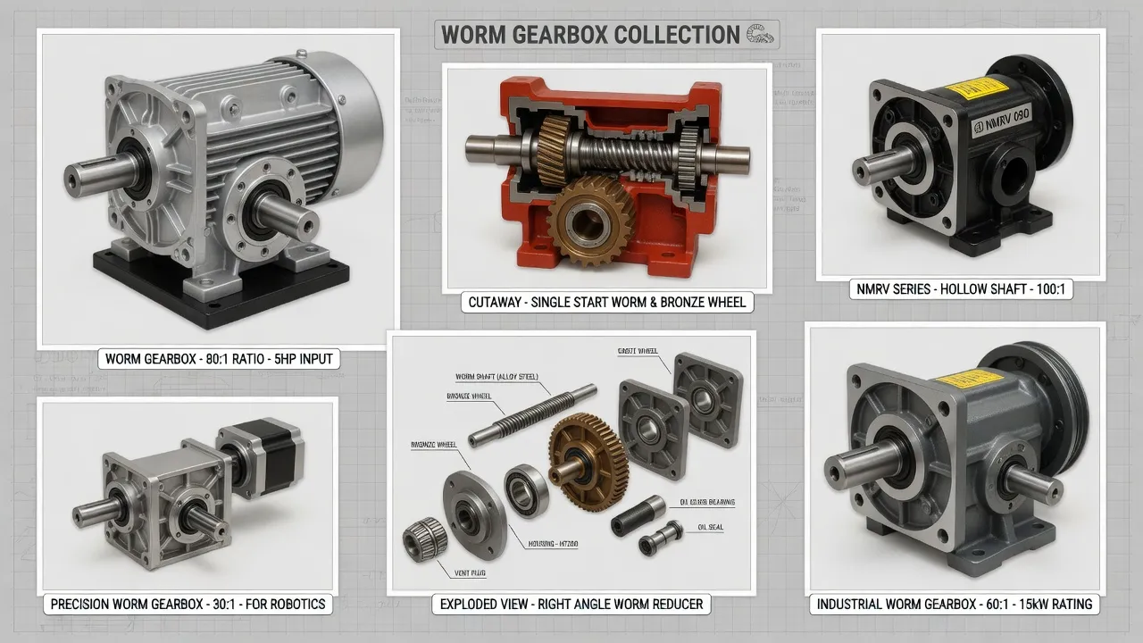
What Drive Demands Distinguish Parabolic Trough Trackers from PV Trackers?
Parabolic trough CSP tracking drives differ fundamentally from PV solar tracker drives across four operational characteristics. The first is the pointing accuracy requirement: PV trackers tolerate 1-2° tracking error with negligible yield impact because flat-plate PV modules absorb sunlight across a broad cosine acceptance angle. Parabolic trough collectors require pointing accuracy below 0.1° because the optical concentration onto receiver tubes runs 70-80× geometric concentration ratio — pointing errors above 0.1° cause focused flux to drift off the receiver tube, dropping thermal collection efficiency by 2 percent per 1° error and producing localized overheating that damages receiver glass envelopes. The drive precision requirements drive specifications toward worm gearbox architecture with ground-and-polished worm thread surfaces (DIN 3974 quality grade Q6 or Q5) rather than the standard Q8 acceptable for PV tracker applications.
The second characteristic is the desert environmental exposure: CSP plants concentrate in high-DNI (direct normal irradiance) regions where dust loading, temperature extremes, and UV exposure exceed typical PV solar conditions. The third is the proximity to high-temperature heat transfer fluid systems — receiver tubes carrying thermal oil at 393°C or molten salt at 565°C run within meters of the tracking drive equipment, with thermal radiation and occasional fluid leak events producing temperature exposure conditions that PV trackers never face. The fourth is the structural torque profile: parabolic trough collector assemblies have substantial mass distributed across long structural members, with the wind torque profile producing different shock loading characteristics than PV tracker structures. The right parabolic trough tracking drive selection addresses pointing precision, desert environmental exposure, thermal proximity, and structural torque simultaneously per precision tracking drive technical references.
How Do Precision Worm Gearboxes Address CSP Tracking Failure Modes?
Ground Worm Threads Deliver Sub-0.1° Pointing Accuracy
Precision worm gearbox architecture using ground-and-polished worm threads at DIN 3974 quality grade Q6 (or Q5 for highest-precision applications) delivers backlash below 4 arc-minutes (0.067°) at the gearbox output — within the 0.1° pointing accuracy budget required by parabolic trough optical performance. Standard Q8 quality grade typical of PV tracker drives produces backlash of 8-12 arc-minutes that would consume the entire CSP pointing accuracy budget on backlash alone before considering structural deflection, control system error, and other contributors. The ground worm threads also produce smoother torque transmission than as-machined alternatives, eliminating the cyclic torque variations that translate to micro-positional errors in standard worm gear architecture.
Self-Locking Maintains Position Without Position Hold Power
Parabolic trough collectors must maintain pointing position absolutely during stationary periods — including during cloud-shadow events that cause control systems to halt tracking, during emergency defocus events when the plant control system needs to drop solar flux quickly, and during overnight stow positions. Self-locking worm gearbox architecture at reduction ratios above 50:1 holds the collector position passively without external brake hardware or active position-hold motor torque, maintaining pointing accuracy across stationary periods regardless of duration. The static self-locking property of the worm gear geometry does not depend on any active mechanism that could fail across the 25-year plant economic life.
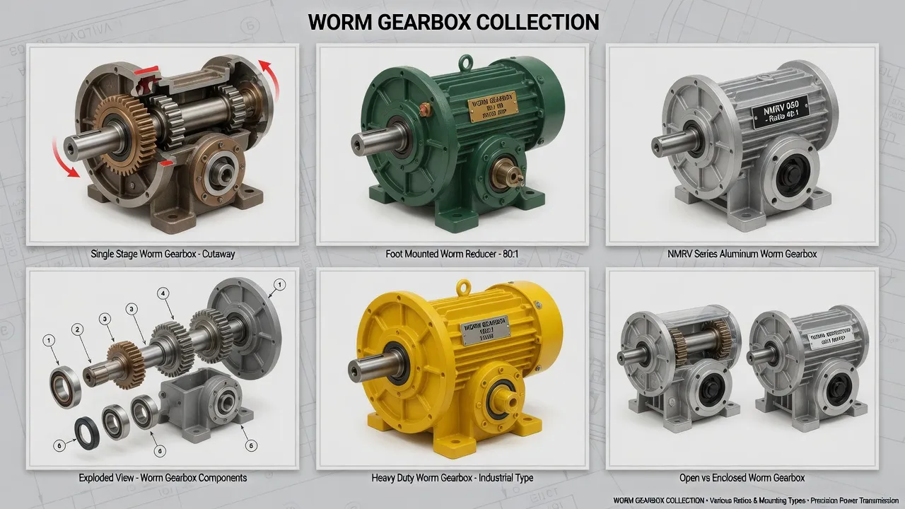
Technical Parameters: CSP Tracking Drive Specification Window
The table below summarizes specifications distinguishing CSP parabolic trough tracking drives from generic industrial worm gearbox alternatives. Values reflect AGMA 6034-B92 worm gear power rating combined with CSP industry conventions for precision tracking and desert site service.
| Parameter | CSP Tracking Spec | Generic Industrial |
|---|---|---|
| Worm thread quality | DIN 3974 Q5 – Q6 ground | Q8 as-machined typical |
| Backlash specification | ≤ 4 arc-min (0.067°) | 8 – 15 arc-min typical |
| Reduction ratio | 50:1 to 80:1 | 5:1 to 100:1 |
| Output torque (rated) | 600 – 4,800 Nm | 200 – 2,000 Nm |
| Operating temperature | -15 °C to +85 °C ambient | -10 °C to +60 °C |
| Sealing rating | IP66 plus dust-resistant | IP54 standard |
| Service factor | 2.5 minimum, 3.5 desert sites | 1.0 – 1.25 typical |
| Design service life | 25 years CSP plant life | 10 – 15 years |
The single specification most often miscalculated on parabolic trough projects is the backlash budget for pointing accuracy. The pointing accuracy budget must account for gearbox backlash plus structural deflection plus control system positioning error plus thermal expansion effects across the diurnal temperature cycle — total budget typically targets 0.1° at the collector, leaving 4 arc-minutes (0.067°) maximum for gearbox backlash alone. Standard worm gearbox specifications produce 8-15 arc-min backlash that exceeds the entire pointing budget on the gearbox contribution alone. Specifying ground worm threads at DIN 3974 quality grade Q6 minimum delivers the precision required for CSP tracking applications.
Application Matrix: Where CSP Tracking Drives Operate
Parabolic Trough Solar Collector Assemblies (SCA)
Parabolic trough solar collector assemblies represent the dominant CSP technology in operation worldwide, with 100-150 meter collector loops grouped into solar fields covering 100-300 hectares per utility-scale plant. Each collector assembly tracks the sun through ±90° azimuth range with the precision tracking drive positioned at the SCA pivot point. Drive output torques range 1,200 to 4,800 Nm depending on collector length and structural design. Self-locking holds collector position absolutely during stationary periods including overnight stow and emergency defocus events. The proximity to thermal oil heat transfer fluid lines at 290-393°C requires drive specifications matching the elevated ambient temperature environment.
Linear Fresnel Reflector (LFR) Tracking
Linear Fresnel reflector CSP technology uses ground-mounted flat mirror strips rather than parabolic curved mirrors, with each mirror strip independently tracked to direct solar flux onto a fixed elevated receiver tube. The drive specifications use compact tracking drives at each individual mirror strip rotation axis, with output torques typically 400 to 1,800 Nm per mirror strip drive. Pointing accuracy requirements parallel parabolic trough at 0.1° per individual mirror strip but with smaller individual structural loading. The deployment count typically multiplies — a 50 MW LFR plant may deploy 4,000-6,000 individual tracking drives compared to 800-1,200 for equivalent parabolic trough capacity.
Solar Tower Heliostat Field Drives
Solar power tower CSP technology uses heliostat fields of individually controlled mirror assemblies that direct solar flux onto a central receiver atop an elevated tower. Each heliostat deploys two precision tracking drives — one azimuth (360° rotational) and one elevation — both required to maintain pointing accuracy of 1-3 milliradians (0.06-0.17°) on the central receiver. Drive output torques range 600 to 2,400 Nm per drive position. The deployment quantity reaches 6,000-12,000 individual drives per 100 MW plant given the typical 1.5-3 m² mirror size and large heliostat field area.
Dish-Stirling and Specialty CSP Trackers
Parabolic dish CSP technology with Stirling engine receivers uses individual precision dual-axis trackers per dish unit, with much higher pointing accuracy requirements (0.05° typical) due to the higher concentration ratios produced by parabolic dish geometry. Drive specifications use precision worm gearbox architecture with the highest-grade ground thread quality (Q5) and backlash below 2 arc-minutes per drive position. Output torques range 1,800 to 4,200 Nm per drive, with the precision specifications dominating drive selection over absolute torque capacity. Reference precision drive specification references for specialty CSP application sizing.
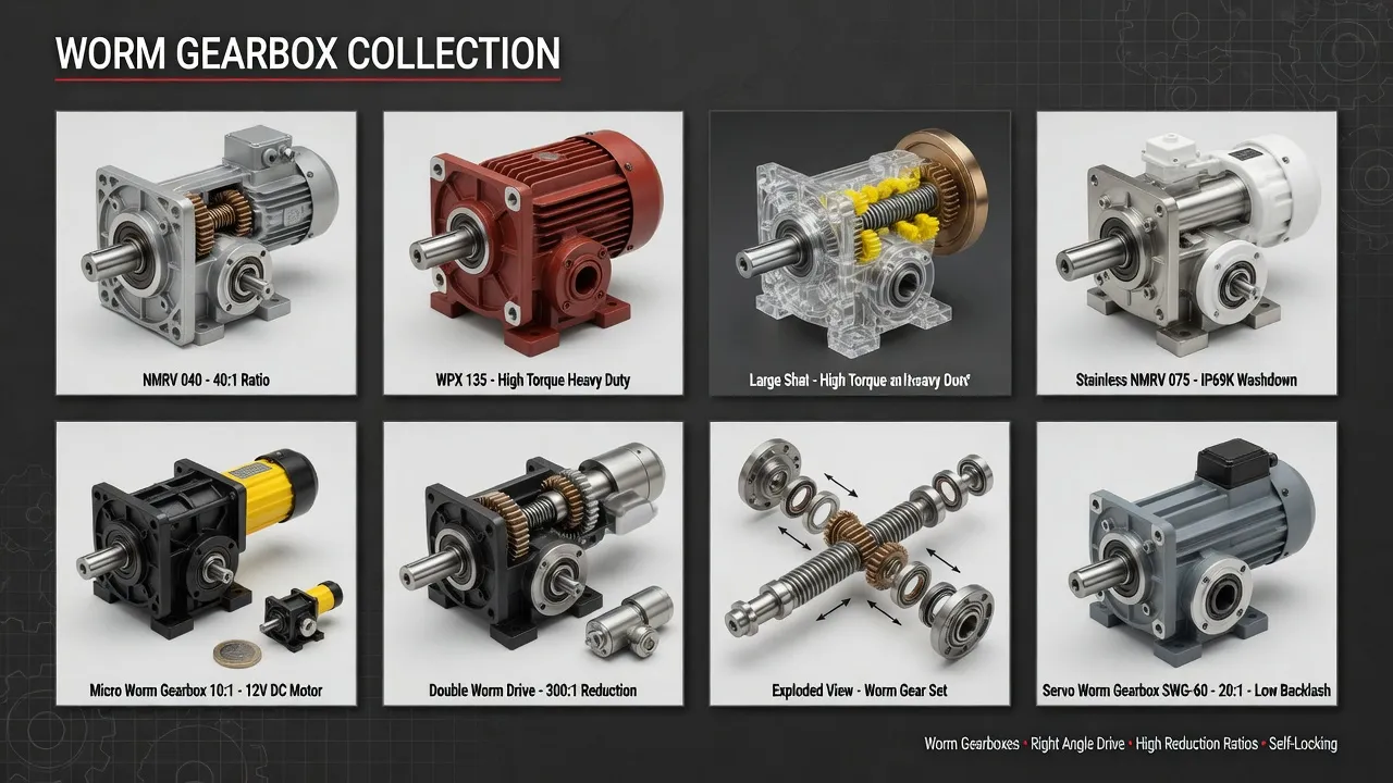
Selection Roadmap: Step-by-Step Workflow
The four-step procedure below covers CSP tracking drive selection from initial requirements documentation through commissioning verification.
Allocate Pointing Accuracy Budget Across Error Sources
Build a pointing accuracy error budget allocating the total 0.1° collector pointing target across gearbox backlash (≤ 4 arc-min), structural deflection under wind loading, control system positioning error, encoder resolution, thermal expansion effects across diurnal cycles, and installation alignment tolerance. The gearbox backlash allocation typically takes the largest single share of the budget, justifying ground worm threads at DIN 3974 quality grade Q6 minimum (or Q5 for highest-precision applications).
Calculate Tracking Torque from Collector Geometry
Determine collector rotational torque from collector mass × center-of-mass distance × gravity component during morning/evening positions plus wind force × structural centroid distance per site design wind velocity. Apply service factor 2.5 minimum for typical CSP installations, 3.5 for desert sites with sustained dust loading and high temperature exposure. The resulting equivalent uniform-duty torque must fall within catalog rating at chosen reduction ratio above 50:1 for self-locking. Document worst-case wind torque at full collector deployment angle.
Specify Desert-Grade Sealing and Wide-Range Lubrication
Order IP66 ingress protection plus desert-grade dust-resistant breather configuration that prevents fine sand particle ingress during sandstorm events. Specify synthetic polyalphaolefin (PAO) lubricant fill rated for -15 °C to +85 °C operating range covering desert site temperature extremes plus elevated ambient near thermal oil heat transfer fluid lines. UV-resistant paint topcoat plus EPDM seal materials rated for 25-year exposure. Specify the sealing and lubricant requirements explicitly on procurement documentation.
Verify Factory Backlash Test Documentation
Confirm factory test reports include measured backlash verification per individual unit (not type-tested batch certification) confirming backlash below the specified arc-minute threshold. Verify gear surface hardness verification per DIN 3974 quality grade certification. The individual-unit backlash verification matters because production tolerance variation across nominally-identical drive units can produce backlash variation that affects pointing accuracy across the CSP solar field even with consistent drive specifications.
Spare Parts Integration: CSP Plant Asset Management
CSP plant O&M operations prioritize spare drive inventory matching the asset management economics of utility-scale installations — typically 2-3 percent of installed drive count carried as forward-deployed spare stock at the plant maintenance facility. The case-hardened 20CrMnTi worm shaft with ground thread surfaces at DIN 3974 quality grade Q6 reaches 28,000+ operating hours under proper synthetic lubrication and IP66 sealing protection — typically translating to 22-25 year service life matching the typical CSP plant economic horizon.
The worm wheel, centrifugally cast from premium tin bronze ZCuSn10P1 per ISO 1338 with ground tooth surfaces, reaches 22,000-28,000 operating hours under proper lubrication. Premium-grade SKF or NSK angular contact bearings handle the combined radial and axial loads with L10 fatigue life exceeding 30,000 hours under rated load. UV-resistant fluoroelastomer (Viton) seal lips with stainless garter springs maintain ingress protection across the 25-year exposure period. Reference precision worm gear motor specifications for matched motor-gearbox tracking package details.
Spare parts kits combining worm shaft, worm wheel, complete bearing set, all shaft seals, gasket kit, breather valve, and synthetic lubricant fill provide complete rebuild capability during scheduled CSP plant maintenance events. Akgnx Co., Ltd ships kits packaged for utility-scale CSP plant inventory practices, with all wear components sourced from the same factory production runs to ensure dimensional consistency and backlash specification consistency across rebuild cycles.

Cost & Sustainability: Total Ownership Across 25-Year CSP Plant Life
CSP plant developers and EPC contractors evaluate tracking drive investments across the project economic life — typically 25 years matching the PPA term. The table compares total cost of ownership for CSP-grade precision tracking drives against generic industrial alternatives across this horizon.
| Cost Component | CSP-Grade Precision | Generic Industrial |
|---|---|---|
| Initial unit price (FOB) | USD 1,200 – 4,800 | USD 480 – 1,800 |
| Service life CSP plant | 22 – 25 years | 8 – 12 years |
| Pointing accuracy hold | ≤ 0.1° throughout life | Degrades after year 3-5 |
| Replacement frequency | 1× over 25 years | 2 – 3× over 25 years |
| Yield loss from drift | Negligible | 2-4% over plant life |
| 25-year cumulative TCO | ~ 1.1× installed cost | ~ 4.5× installed cost + yield loss |
Sustainability and compliance documentation accompanies every CSP-grade precision tracking drive shipment. The housing carries CE marking per EU Machinery Directive 2006/42/EC and complies with RoHS Directive 2011/65/EU. Manufacturing follows ISO 9001:2015 quality management procedures with full material traceability from bronze worm wheel chemical composition through case-hardened worm shaft heat-treatment records. Worm gear tooth geometry follows DIN 3974 quality grade Q6 (or Q5 on request) with load capacity per AGMA 6034-B92 worm gear power rating methodology adjusted for CSP service factor.
Synthetic polyalphaolefin (PAO) lubricant fills produce 70 to 80 percent less waste oil over the equipment service life compared to mineral oil alternatives requiring frequent changes — a meaningful sustainability metric for utility-scale CSP plants subject to lifecycle environmental assessment requirements. The pointing accuracy hold across 25-year service life eliminates the 2-4 percent cumulative yield loss that gradual drift produces with generic industrial tracking drives. Akgnx Co., Ltd manufactures CSP-grade precision tracking drives through a dedicated solar thermal drive program serving CSP technology providers, EPC contractors, and CSP plant O&M operators across major solar thermal markets globally.
Customer Testimonials from CSP Plant Operations
“Our 110 MW parabolic trough CSP plant deploys 962 solar collector assemblies across 195 hectares of desert solar field. We selected the VRV030-based precision tracking drives during the 2019 specification review after evaluating four alternative suppliers across an instrumented prototype installation. Six years into operation, our drive replacement rate is running 0.4 percent annually with measured pointing accuracy remaining within our 0.08° design budget across the operating fleet.”
— Plant Manager, Utility-Scale CSP Operator, Spain
“As a parabolic trough CSP technology provider serving utility-scale projects globally, we evaluated multiple precision worm gearbox suppliers for our standard SCA tracking drive package. Akgnx VRV030-based drives passed our 12,000-cycle accelerated life test simulating 25-year tracking duty plus desert dust exposure cycles — measured backlash growth under 1 arc-minute at test completion. Akgnx held our annual production schedule across two consecutive years for SCA shipments to our Spanish, Moroccan, and Chilean customer projects.”
— Director of Engineering, CSP Technology Provider, Germany
“We replaced original tracking drives across 380 SCAs at our 2010-vintage CSP plant after the original supplier’s units showed pointing accuracy degradation beyond year 8 that translated to measurable thermal yield loss. The VRV030-based replacement drives mounted to existing SCA brackets and supported our crew installation rate of 12 drive replacements per crew-day during the rolling swap-out program. Restored pointing accuracy improved annual thermal yield by approximately 1.8 percent across the affected portion of the solar field.”
— Asset Manager, CSP Plant Portfolio, Morocco
“Our 50 MW LFR demonstration plant uses 4,800 individual mirror strip tracking drives, each requiring sub-0.1° pointing accuracy. The VRV030 specifications passed our prototype qualification testing including IEC 60068-2 environmental simulation across the desert site temperature and humidity ranges. Drive availability across 4 years of commercial operation has measured 99.94 percent — substantially better than our pre-construction availability assumptions used during the project financial modeling phase.”
— Project Director, LFR Demonstration Plant, Australia
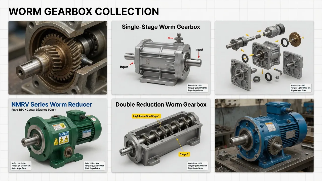
Recommended Drive: VRV030 Precision Worm Gearbox for CSP Tracking
For CSP parabolic trough and linear Fresnel reflector tracking applications across utility-scale solar thermal plants, solar tower heliostat fields, and specialty CSP installations, the VRV030 Precision Worm Gearbox in CSP specification targets the 0.1° pointing accuracy, 25-year-service desert installation class with engineering features specifically chosen to address the failure modes that retire generic worm gearbox alternatives within 8-12 years of CSP plant installation.
Specifications include cast iron housing with two-coat industrial epoxy paint plus UV-resistant topcoat rated for 25-year desert outdoor exposure, ground-and-polished worm threads at DIN 3974 quality grade Q6 (or Q5 on engineering request) delivering measured backlash below 4 arc-minutes per individual unit, centrifugally cast tin bronze ZCuSn10P1 worm wheel meshing with case-hardened 20CrMnTi steel worm shaft hardened to HRC 58-62 surface, fluoroelastomer (Viton) double-lip seals with stainless garter springs at all shaft penetrations, IP66 ingress protection plus desert-grade dust-resistant breather configuration, synthetic polyalphaolefin (PAO) lubricant fill rated for -15 °C to +85 °C operating temperature range, and stainless steel A2 mounting hardware throughout. Reduction ratios from 50:1 through 80:1 maintain reliable static self-locking across the full CSP tracking duty range. Output torque on the VRV030 frame reaches 4,800 Nm continuous with self-locking holding torque to 1,200 Nm. CE marking, RoHS compliance, and ISO 9001:2015 quality system certification ship with every unit, with individual-unit backlash measurement reports included on every shipment.
Beyond the VRV030 frame, complete CSP tracking drive packages typically pair the precision gearbox with stepper motor or servo motor drive configurations supporting the precise positioning control required by CSP control systems, weatherproof control connection junction box rated for 25-year desert outdoor exposure, absolute encoder feedback for closed-loop pointing position verification, and full stainless steel A2 mounting hardware throughout. Akgnx Co., Ltd supplies matched drive packages for CSP technology providers and provides aftermarket replacement units for installed CSP plant fleets across major solar thermal markets globally.
Specifying Tracking Drives for CSP Plants?
Send collector type, pointing accuracy budget, project size, and required output torque. We supply VRV030-based precision worm gearboxes engineered for sub-0.1° tracking and 25-year CSP plant service.
Frequently Asked Questions
© Akgnx Co., Ltd · About Us · Contact Us · [email protected]